C.E. Niehoff & Co. N2013 Installation User Manual
N2013 battery isolator, Alternator, Installation instructions
II0139A
Page 1 of 2
N2013 Battery Isolator
Installation Instructions
1. Install N2013 in location specified by vehicle
manufacturer, using mounting hardware and
torque specified by vehicle manufacturer.
Do not exceed recommended
torque. Component damage
will
result.
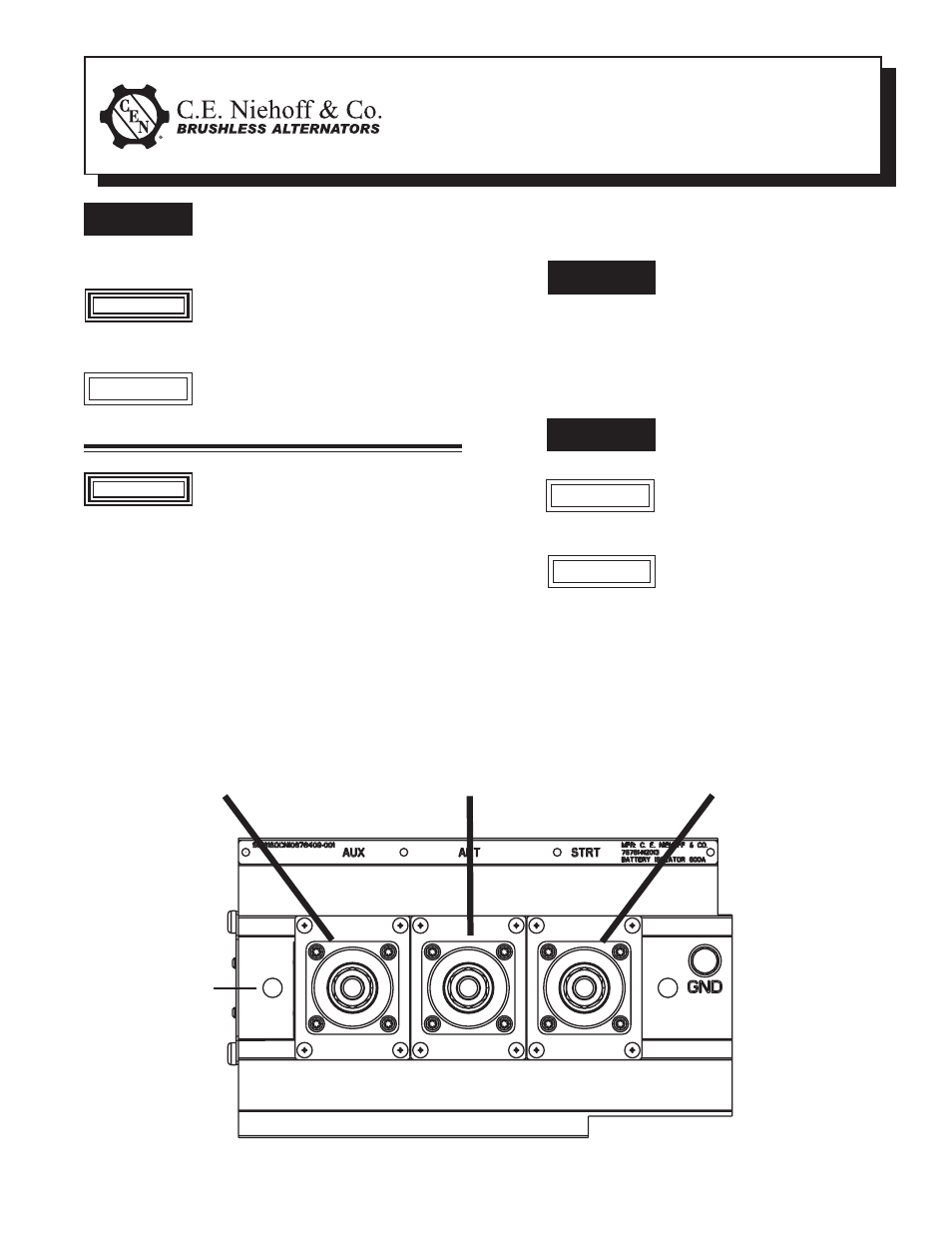
2. Connect number of cables and cable placement as
specified by vehicle manufacturer. See Figure 1 for
reference. Use proper stacking order as specified
by vehicle manufacturer. Tighten to specifications
shown in Figure 2 on page 2.
Do not exceed recommended
torque. Component damage
will
result.
Typically, no more than two cables
per terminal are recommended for
the power carrying capacity of the
terminal.
Support cables as specifi ed by
vehicle manufacturer. Failure to do
so can cause component damage.
3. Test components to make sure they operate
properly.
This symbol is used to indicate the
presence of hazards that can cause
minor personal injury or equipment
damage.
This symbol is used to indicate the
presence of hazards that will cause
severe personal injury, death or
equipment
damage.
DANGER
DANGER
DANGER
CAUTION
T
T
This symbol is used to indicate the
presence of hazards that can cause
severe personal injury, death or
equipment
damage.
WARNING
CAUTION
Disconnect alternator, batteries, and
any other auxillary equipment before
removing cables. Failure to do so can
result in severe personal injury.
WARNING
M10 hardware
(2 places) –
torque to
15 Nm/11 lb.ft.
T
Figure 1 - Cable Locations
Alternator
T
See Vehicle Manufacturer
Specifi cations for
Cable Identifi cation
at This Location
CAUTION
See Vehicle Manufacturer
Specifi cations for
Cable Identifi cation
at This Location