C.E. Niehoff & Co. N1388: N7153 Control Unit Assembly/ N7155 B+ Output Stud Replacement Instructions User Manual
Page 2
19. Apply bead of Dow Corning® SE9186L RTV coating
or equivalent on mating surfaces between control
unit assembly and drive end housing.
20. Install control unit assembly in cavity. Use a suit-
able adhesive such as Loctite® 222 on screws.
Torque mounting screws to 2.3 Nm/20 lb. in.
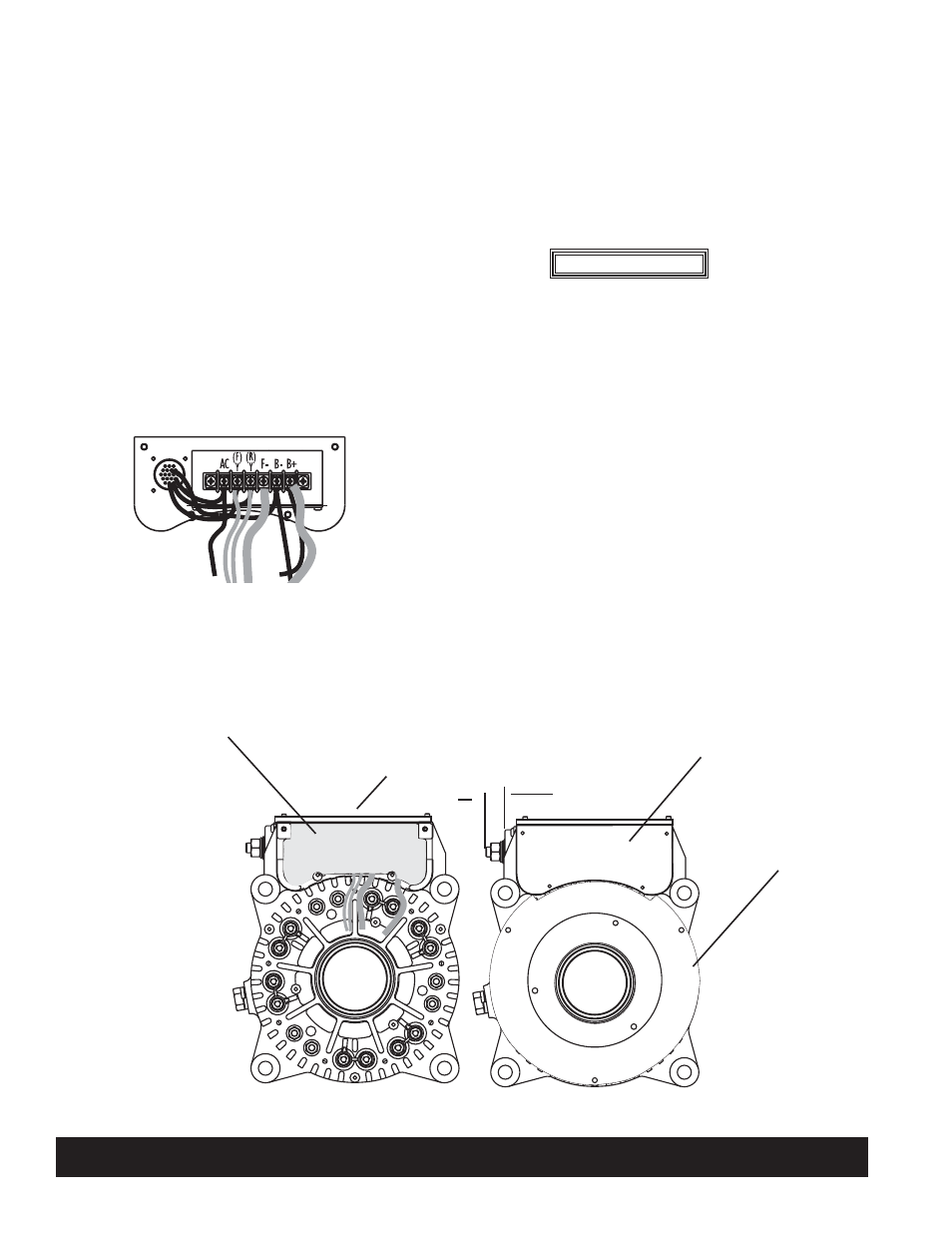
21. Reconnect wiring removed from terminal strip.
See Figure 1 on page 1 and Figure 3 below.
Torque screws to 1.2 Nm/10 lb. in.
22. Apply bead of Dow Corning® SE9186L RTV
coating or equivalent on mating surfaces between
top control unit cover plate and drive end housing.
23. Re-install top control unit cover plate. Use a suit-
able adhesive such as Loctite® 222 on screws.
Torque mounting screws to 2.3 Nm/20 lb. in.
24. Turn alternator on anti-drive end and brace to
prevent movement. Press down all exposed wiring
so they will be covered by replacement potting.
WARNING
V
Top
control unit
cover plate
V
Control unit
cover plate
C. E. Niehoff & Co. • 2021 Lee Street • Evanston, IL 60202 Tech Services Hotline 800-643-4633
Figure 4 – Replacing Control Unit Assembly and/or B+ Terminal on N1388 Alternator
II0114B
Page 2 of 2
25. Fill the cavity inside the control housing with GE
Silicones® RTV11® silicone 2-part system:
a. Mix 148 drops (0.1 ounce) of cure per 1 cup of
RTV. Mix well to prevent incomplete deep-set.
At this point, there is a half hour before mixture
thickens and two hours until mixture deep-sets.
b. Pour mixture into cavity until it covers the
terminal screws on the terminal strip. Make
sure all screws are covered with new potting
material.
Product warranty will be
void if cavity is not fi lled as
indicated in step 25.
26. When new potting is dry, re-install control unit
cover plate and drive end housing cover plate. Use
a suitable adhesive such as Loctite® 222 on screws.
Torque mounting screws to 2.3 Nm/20 lb. in.
27. Re-install voltage adjust plug in appropriate position
for use.
28. If B+ terminal was replaced, re-install external
hardware. Use a suitable adhesive such as Loctite®
222 on the middle of stud threads. Screw stud into
terminal until only 11/16" is protruding from sur-
face of terminal. See Figure 4.
V
New potting
Figure 3 – Reattaching Wiring to Terminal Strip
V
V
See step
28 above
V
Drive end
cover plate