C.E. Niehoff & Co. N1381: N7300 Replacement Kit Instructions User Manual
N1381 alternator, C. e. niehoff & co, Conversion instructions
Page 1
II0068A
N1381 Alternator
Conversion Instructions
C. E. Niehoff & Co.
BRUSHLESS ALTERNATORS
Using N7300 Conversion Kit
The following term is used to bring attention to the presence of hazards of various risk levels or to important information con-
cerning product life.
Indicates the presence of hazards that will cause severe personal injury, death, or substantial
property damage if ignored.
DANGER
DANGER
Disassembly
1. Disconnect B+ cables from inside the control
unit.
2. Unsolder resistor wires from modules.
3. Remove potting from control unit.
4. Remove screws holding control unit assembly to
housing.
5. Remove and discard control unit assembly.
6. Clean old potting from inside control unit.
Assembly
1. Attach new control unit assembly (see Figure 1)
to housing. Use suitable adhesive, such as
Loctite® 222. Follow manufacturer’s instruc-
tions. Torque new hardware to 5 Nm/45 lb. in.
2. Connect B+ cables inside the control unit.
Torque hardware to 15 Nm/135 lb. in.
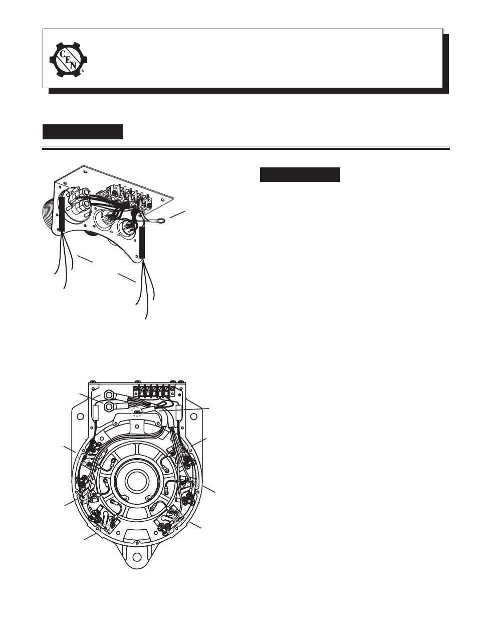
3. Using hardware provided in kit, attach ground
terminal lead from control unit terminal strip to
threaded hole in top of casting. See Figure 2.
Torque new hardware to 5 Nm/45 lb. in.
4. Using standard solder, connect the six resistor
leads to the points shown in Figure 2.
Figure 1—New Control Unit Assembly
T T T T T
Ground
terminal lead
T T T T T
Resistor
leads
TTTTT
Do not allow hardware to drop
inside alternator. Loose hard-
ware inside alternator cavity or
stator windings or field coil
will cause substantial
equipment damage.
Resistor
lead
TTTTT
Ground
terminal
lead
T T T T T
Resistor
lead
TTTTT
Resistor
lead
TTTTT
Resistor
lead
T T T T T
Resistor
lead
T T T T T
Resistor
lead
T T T T T
Figure 2—Drive End (DE) Housing Connections
B+
cables
TTTTT
TTTTT