C.E. Niehoff & Co. EPM Installation User Manual
Electric power manager (epm), C. e. niehoff & co
II0043A
Page 1 of 2
Electric Power Manager (EPM)
Installation Instructions
C. E. Niehoff & Co.
BRUSHLESS ALTERNATORS
1. Install EPM in location specified by vehicle manufac-
turer. Torque mounting hardware to 3.39 Nm/
30 lb. in. See Figure 2 on page 2.
Do not exceed recommended
torque. Component damage
will result.
2. Connect cables as shown in Figures 1 and 2 in
proper stacking order. Tighten to specifications
shown in Figure 2.
Do not exceed recommended
torque. Component damage
will result.
Support cables within 305 mm/
12 in. of EPM. Failure to do so can
cause component damage.
3. Simple wiring schematic is shown on page 2.
4. Test components to make sure they operate properly.
This symbol is used to indicate the
presence of hazards that can cause
minor personal injury or equipment
damage.
This symbol is used to indicate the
presence of hazards that will cause
severe personal injury, death or
equipment damage.
DANGER
DANGER
DANGER
CAUTION
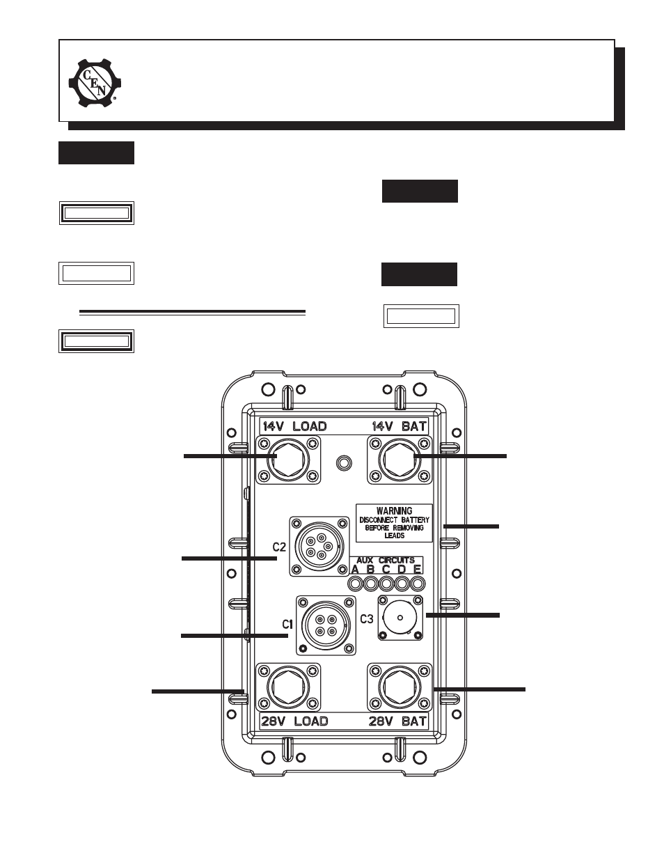
14 V
FROM
LOAD
TTTTT
TTTTT
14 V
FROM
BATTERY
EPM
CIRCUITS
CONNECTOR
TTTTT
28 V
FROM
LOAD
TTTTT
TTTTT
28 V
FROM
BATTERY
Figure 1 - Cable Arrangement (See Wiring Diagram on Page 2)
AUX
CIRCUITS
CONNECTOR
TTTTT
TTTTT
CAN/J1939
CONNECTOR
Cap must be
kept in place
when connector
is not in use
TTTTT
LABEL:
WARNING
Disconnect battery
before removing
leads
This symbol is used to indicate the
presence of hazards that can cause
severe personal injury, death or
equipment damage.
WARNING
CAUTION
Disconnect battery before removing
leads.Failure to do so can result in
severe personal injury.
WARNING