C.E. Niehoff & Co. N1126-1 Alternator Installation User Manual
C. e. niehoff & co
N1126-1 Alternator/N3034 Regulator
OEM Wiring Connections
Installation Instructions
C. E. Niehoff & Co.
BRUSHLESS ALTERNATORS
This symbol is used to indicate
presence of hazards that can cause
minor property damage.
CAUTION
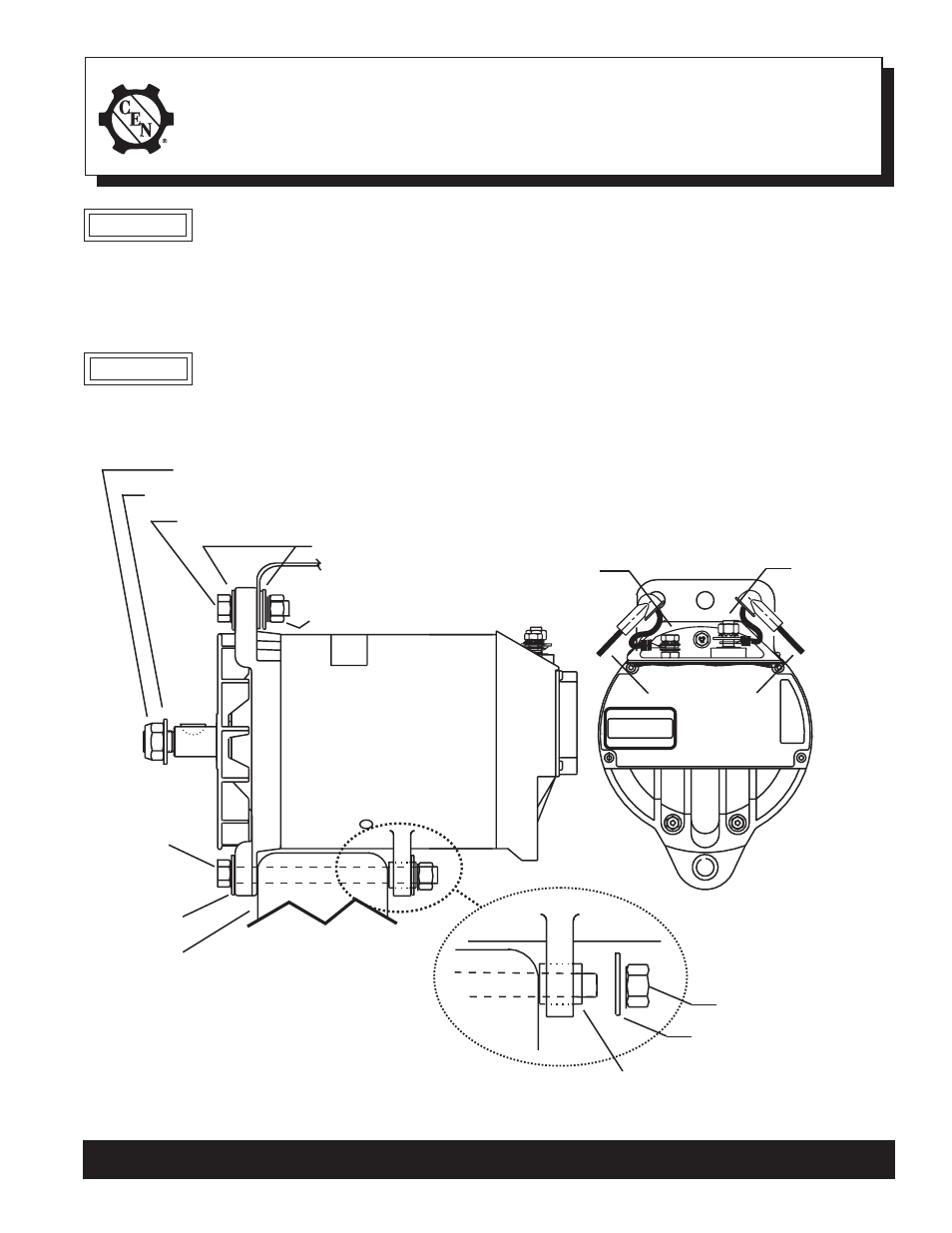
Install N1126-1 alternator as shown in Figure 1:
Slip bushing located in rear mounting
foot must be securely tightened against
alternator mounting bracket on engine. Failure to do so
can result in broken mounting feet or broken upper
mounting bracket.
Figure 1 - N1126-1 Alternator Installation Details
CAUTION
1. Units are shipped with shaft collar, hardened
washer and locknut. Remove and discard shaft
collar. Install pulley and furnished hardened
washer. Torque locknut to 136 Nm/ 100 lb. ft.
2. Use hardened washers between aluminum surfaces
and bolt heads and nuts. Torque mounting bolts to
80 Nm/60 lb. ft.
3. All cabling, wiring or conduit must be supported
within 305 mm/12 in. of termination on alternator.
4. Choose wire gauge for B+ and B– cables capable of
handling maximum alternator output with minimum
voltage drop.
B+ terminal
0.3125-18 locknut –
torque to
9 Nm/80 lb. in.
T T T T T
B– terminal
0.25-20 locknut –
torque to 9 Nm/80 lb. in.
T
T
T
T
T
12mm/0.50 Locknut –
torque to
80 Nm/60 lb. ft.
T T T T T
Hardened washer
T T T T T
Slip bushing must be tightened against
bracket — see “CAUTION” above
T T T T T
0.625 - 18 Locknut
torque to 136 Nm/100 lb.ft.
T T T T T
T T T T T
Hardened washer
12mm/0.50 in.
mounting bolt
(full length)
TTTTT
Hardened
washer
TTTTT
Bracket
on engine
Alternator
mounting
bracket
on engine
TTTTT
T T T T T
12mm/0.50 in. Mounting bolt
Hardened washers
T T T T T
12mm/0.50 Locknut –
torque to 80 Nm/60 lb. ft.
TTTTT
T
T
T
T
T
T
T
T
T
T
T T T T T
Customer cables
w/terminal boots
II0060A
Page 1 of 1
C. E. Niehoff & Co. • 2021 Lee Street • Evanston, IL 60202 Tech Services Hotline 800-643-4633