C.E. Niehoff & Co. C803D/C840D Alternator Retrofit/Upgrade Installation User Manual
Retrofit/upgrade installation instructions, Ii65g page 1 of 2
Retrofit/Upgrade Installation Instructions
C803D and C840D
Alternators
This symbol is used to indicate the presence
of hazards that can cause minor personal
injury or property damage.
CAUTION
* Use this setpoint to maintain proper battery charge level during
shorter operating cycles.
Table 1 — A2-330/A2-336 Regulator Voltage Selector Switch Position
Switch Position
Battery Type
1
27.5 V
Maintenance
2
28.0 V
Maintenance*
3
28.5 V
Maintenance-Free
4
29.0 V
Maintenance-Free*
If an extended wiring harness is supplied with
alternator and regulator, see separate instruc-
tions packed with harness.
This symbol is used to indicate the presence
of hazards that can cause severe personal
injury or substantial property damage.
WARNING
Table 2 — A2-346 Regulator Voltage/Battery Switch Position
Switch
Position
A9-4036 Harness
Not Connected
(Voltage Select)
A9-4036 Harness
Connected (Battery Select)
1
27.5 V
Maintenance (D Catergory)
2
28.0 V
Maintenance-free (Group 31)
3
28.5 V
AGM
4
29.0 V
DO NOT USE POSITION # 4
A2-346 regulator is flat-temperature compensated.
A2-346 28 V regulator can be used with or with-
out A9-4036 temperature-voltage sense/J1939
harness from the vehicle.
• When A9-4036 temperature-voltage sense/
J1939 harness is not connected, regulator will
operate in fixed voltage setting determined
by the select switch position on the bottom of
the regulator. See column 2 in Table 2.
• When A9-4036 temperature-voltage sense/
J1939 harness is connected, regulator will
automatically optimize the charge voltage for
battery type based on temperature. See col-
umn 3 in Table 2 and select switch position
based on battery type.
Regulator is factory-set to Position 1. To change, remove regu-
lator, turn regulator over, and select appropriate switch
position (see NOTICE above and Table 2). Re-install regulator
on alternator. Torque screws to 8.5 Nm/75 lb in.
NOTICE
This symbol is used to indicate special instruc-
tions on installation, operation, or maintenance
that are important, but not related to per-
sonal injury hazards.
NOTICE
II65G
Page 1 of 2
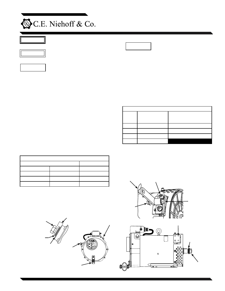
Figure 1 - Alternator Installation Details
B+ terminal –
see inset above
B– terminal M10 bolt –
torque to 15 Nm/11 lb. ft.
M20 nut–torque to
163 Nm/120 lb. ft.
Disc spring
washer
B+ terminal M12 bolt –
torque to 30 Nm/22 lb. ft.
Battery output
cable terminal
Washer
Lock washer
Dampening bracket mount –
see inset above
Non-louvered duct opening to attach
fresh air intake pipe. See Step 7, page 2.
M10 x 1.5 bolt, lockwasher, washer: 2 places –
torque to 27 Nm/20 lb. ft.
Secure to
engine block
(see step 2c above)
Bolt and washer
torque to
57 Nm/42 lb. ft.
Nut
1. Turn off battery switch or disconnect battery ground cable.
2. Remove alternator drive belt.
3. Remove all oil lines between alternator and engine. Plug oil
line outlets with properly-sized pipe or tubing plugs. Remove
oil drain hose at existing alternator and plug opening.
4. Label wires for identification, then disconnect electrical con-
nections from existing alternator.
5. Remove alternator mounting bolts and existing alternator
from mounting bracket.
6.
A2-330/A2-336 regulators are flat-temperature compensated
and are factory-set at lowest setting to accommodate 8D
batteries. For other batteries:
a. Remove regulator from housing and change position on
voltage selector switch. See Table 1.
b. Re-install regulator on drive end housing, and torque
mounting screws to 8.5 Nm/75 lb. in.
7. Units are shipped with shaft collar, Belleville washer and
nut. Remove and discard shaft collar. Install pulley and
furnished Belleville washer. Torque nut to 162.7 Nm/
120 lb. ft.