C.E. Niehoff & Co. C725 Retrofit/Upgrade Installation User Manual
C725 alternator, Retofit/upgrade installation instructions
C725
Alternator
Retofit/Upgrade Installation Instructions
Page 1 of 1
II209A
This symbol is used to indicate the
presence of hazards that can cause minor
personal injury or property damage.
CAUTION
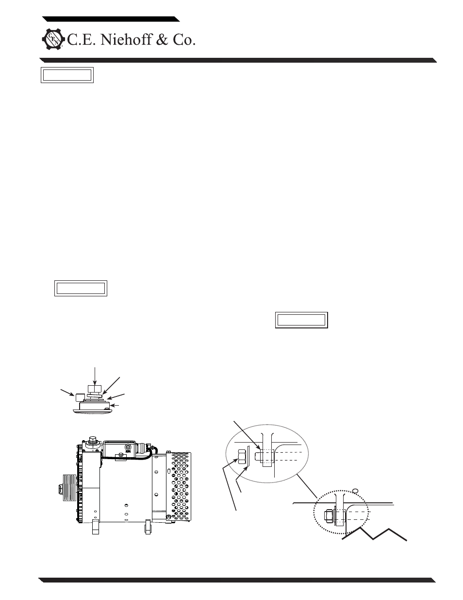
Install new C725 alternator (seee Figure 1)
Slip bushing located in rear mounting
foot must be securely tightened against
alternator mounting bracket on engine.
Failure to do so can result in broken
mounting feet or broken upper mounting
bracket.
1. Install A2-329 regulator on shell of C725 alterna-
tor and torque mounting screws to 8.5 Nm/75 lb. in.
CAUTION
Figure 1 - C725 Alternator Installation Details
Hardened washer
12mm/0.50 Locknut –
torque to
88 Nm/64 lb. ft.
Slip bushing must be
tightened against
bracket —
see “CAUTION” above
Bracket
on engine
Terminal bolt–torque to 23 Nm/17 lb. ft.
Washer
(on B+ bolts only)
Battery cable
terminal
Lockwasher
Insulator
Alternator 14 V/ 28 V B+ Terminal Studs
and Alternator B
– Terminal Stud
CAUTION
C725
Alternator
Remove existing alternators
1. Turn off battery switch or disconnect battery
ground cable.
2. Remove alternator drive belt.
3. Remove all oil lines between alternator and
engine. Plug oil line outlets with properly-sized
pipe or tubing plugs. Remove oil drain hose at
existing alternator and plug opening.
4. Label wires for identification, then disconnect
electrical connections from existing alternator.
5. Remove 28 V alternator mounting bolts, cables,
and existing 28 V alternator/regulator.
6. Remove 14 V alternator mounting bolts, cables,
and existing 14 V alternator/regulator. Tape all
cables from 14 V alternator except the 14 V B+
connection, which will be connected to the new
alternator.
2. Units are shipped with shaft collar, hardened
washer and nut installed. Remove and discard
shaft collar. Install pulley, furnished hardened
washer, and nut. Torque nut to 162.7 Nm/120 lb. ft.
3. Use hardened washers between aluminum
surfaces and bolt heads and nuts.
4. Follow vehicle manufacturer’s recommenda-
tions for belt tension.
5. All cabling, wiring or conduit must be supported
within 305 mm/12 in. of termination on alternator.
6. Choose wire gauge capable of handling maximum
alternator output with no more than 0.4 V drop
(28 V)/ 0.2 V drop (14 V) on each leg from alterna-
tor to battery.
7. Make electrical connections to CEN regulator,
using proper ring terminals.
a. Make sure alternator-to-regulator harnesses
are plugged securely in regulator receptacles.
b. Connect IGN terminal on regulator to 28 V
keyed ignition switch source. Torque #10-32
terminal nut to 3.4 Nm/30 lb. in.
8. Make electrical connections to alternator:
a. Connect battery positive cables from vehicle
to alternator 28 V B+ and 14 V B+ terminals.
Torque both 0.50-18 UNC-2A terminal bolts
on alternator to 23 Nm/17 lb. ft.
B+ cables must be supported by
cable clamps within 12’’ of both
B+ output terminals to avoid
premature failure of B+ output
terminals. CEN recommends
using cable clamps attached to
alternator anti-drive end housing
for
support.
b. Connect ground cable from vehicle to alter-
nator B– terminal. Torque 0.3750-16 UNC-2A
B– terminal bolt on alternator to 23 Nm/17 lb. ft.
If you have questions about your alternator or any of these instructions, or if you need to locate a Factory Authorized Service Dealer, please contact us at:
C. E. Niehoff & Co.• 2021 Lee Street • Evanston, IL 60202 USA
TEL: 800.643.4633 USA and Canada • TEL: 847.866.6030 outside USA and Canada • FAX: 847.492.1242
E-mail us at [email protected]