C.E. Niehoff & Co. C717, C717-1, C717-2 Installation User Manual
Installation instructions
II215A
Page 1 of 1
C717, C717-1, and
C717-2 Alternator
Installation Instructions
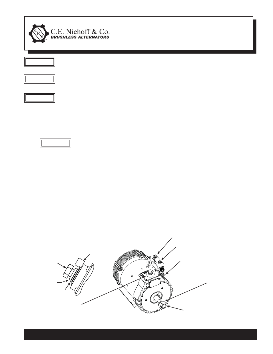
Figure 1 - C717-1 Alternator Installation Details
C. E. Niehoff & Co. • 2021 Lee Street • Evanston, IL 60202 Tech Services Hotline 800-643-4633
1. Install
alternator:
a. Carefully place alternator on alternator
mounting
bracket.
Use caution when lifting
alternator to prevent possible
minor personal injury. Use hoist
along with alternator lifting ring
located on top of alternator.
b. Secure alternator to alternator mounting
bracket using four .5000-13 UNC-2A, grade 5
or higher mounting bolts with lock washers.
Mounting bolts should extend 17.8/25.4 mm
(0.7/1.0 in.) into alternator mounting rail.
Torque mounting bolts to 88 Nm/65 lb. ft.
2. Units without pulley are shipped with shaft collar,
disc spring washer, and nut. Customer should
replace shaft collar pulley and secure with hard-
ware furnished from factory. Torque hardware
to 163 Nm/120 lb. ft. Some units are already
shipped with pulley installed and torqued to
proper value.
CAUTION
This symbol is used to indicate presence
of hazards that can cause minor property
damage.
CAUTION
B+ terminal –
see inset above
B– terminal M10 bolt –
torque to 15 Nm/11 lb. ft.
B+ terminal M12 bolt –
torque to 30 Nm/22 lb. ft.
Battery output
cable terminal
Washer
Lock washer
M20 fl ange nut–
torque to 163 Nm/120 lb. ft.
Disc spring
washer
D+ terminal M6 nut – torque to
4.5 Nm/40 lb. in.
IGN terminal M5 nut – torque to
4.5 Nm/40 lb. in.
3. Install alternator drive belt and secure belt ten-
sion bracket assembly. Loop alternator drive belt
over pulleys and align belt with polyvee grooves.
Follow vehicle manufacturer’s recommendations
for belt tension.
4. All cabling, wiring or conduit must be supported
within 305 mm/12 in. of termination on alternator.
5. Choose wire gauge capable of handling maxi-
mum alternator output with no more than 0.4 V
drop on each leg from alternator to battery.
6. Regulator is furnished with OEM units and is
supplied separately by request with aftermarket
units. Mounting screws on regulator should be
torqued to 8.5 Nm/75 lb. in.
7. Make electrical connections to CEN regulator as
required, using proper ring terminals (follow
vehicle manufacturer’s diagram and separate
instructions packed with extended wiring
harness when used):
a. Make sure alternator-to-regulator harness
is plugged securely in regulator receptacle.
b. A2-351 regulator furnished with some units
has additional J1939 connector to vehicle.
Securely attach additional vehicle cable to
this connector as required.
This symbol is used to indicate presence
of hazards that can cause severe personal
injury or substantial property damage.
WARNING
The C717 alternator has maximum ambi-
ent operating temperate range of 65°C/
149°F. Operating above this temperature
range may cause irreparable damage to
the
alternator.
WARNING