C.E. Niehoff & Co. A3-201 Adjustable Pulley Installation User Manual
Page 2
II0075A
Page 2 of 2
C. E. Niehoff & Co. • 2021 Lee Street • Evanston, IL 60202 Tech Services Hotline 800-643-4633
a. Locate number of spacers required between pulley faces due to belt size (Step 2) on the top of the chart.
b. Look down column located in step A until desired belt spacing dimension is found.
c. In the left hand column, opposite dimension located in step B, find the required number of spacers to be
inserted between pulleys.
EXAMPLE: Belt size 1/2 inch—required spacers between each pulley face: 2. Belt spacing: 1 inch.
Spacers between pulley: 4 (from graph below).
No. of Spacers Between Each Pulley Face
No. of Spacers
Between Pulleys
0
1 2 3 4 5 6
0
5/8
11/16 3/4 13/16 7/8 15/16 1
1
11/16
3/4 13/16 7/8 15/16 1 1-1/16
2 3/4
13/16
7/8
15/16
1
1-1/16
1-1/8
3 13/16
7/8
15/16
1
1-1/16
1-1/8
4 7/8
15/16
1
1-1/16
1-1/8
1-3/16
5 15/16
1
1-1/16
1-1/8
1-3/16
6
1
1-1/16 1-1/8 1-3/16 1-1/4
7 1-1/16
1-1/8
1-3/16
1-1/4
8 1-1/8
1-3/16
1-1/4
1-5/16
9 1-3/16
1-1/4
1-5/16
10 1-1/4
1-5/16
1-3/8
11 1-5/16
1-3/8
12 1-3/8
1-7/16
13 1-7/16
14 1-1/2
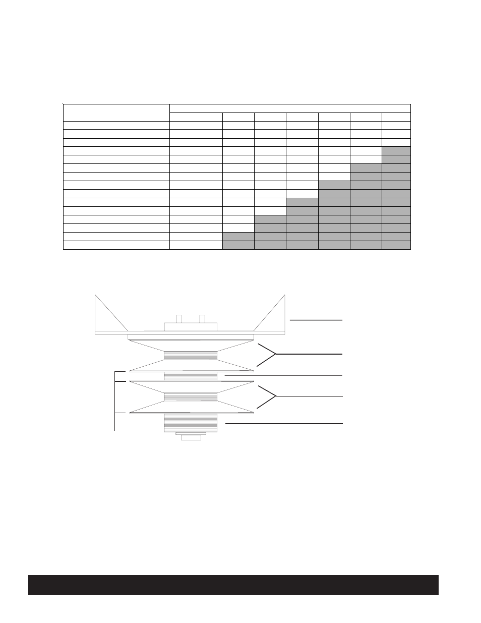
Assembling Pulley (Use All Spacers)
1. Assemble extra spacers to hub.
2. Assemble first pulley.
3. Assemble spacers for belt spacing as required.
4. Assemble second pulley (gold pulley is always next to fan).
5. Assemble fan and backing plate, and tighten screws securely.
TTTTT
1
2
T
TT
T
T
T
TT
T
T
TTTTT
3
4
T
TT
T
T
T
TT
T
T
TTTTT
5
TTTTT
D
TTTTT
TTTTT