Trouble shooting – C.E. Niehoff & Co. A1-102/A1-104 Installation User Manual
Page 2
C. E. Niehoff & Co. • 2021 Lee Street • Evanston, IL 60202 Tech Services Hotline 800-643-4633
II163A
Page 2 of 2
Use Fan & Pulley Assembly: A3-300, A3-301, A3-302, A3-303; or, Fan A3-101 with A3-403 Bushing and A3-202 or A3-203 Pulley.
Any keyed alternator pulley with appropriate dimensions can be used with A3-403 Bushing and A3-101 Fan.
FAN AND PULLEY INFORMATION
Re-establishing magnetic field.
If no output is obtained - See Service Manual for specific alternator test.
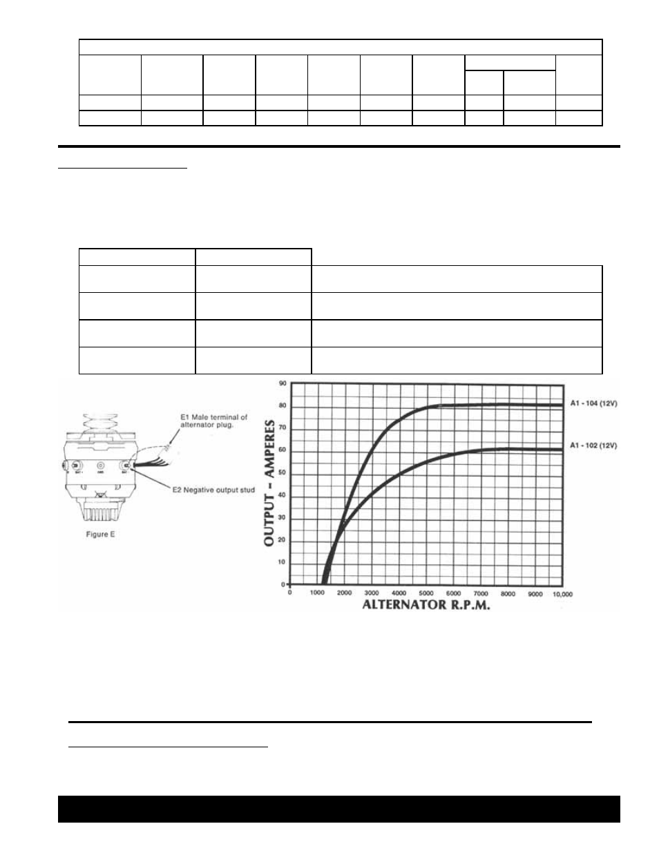
With engine running, disconnect plug between alternator and regulator and momentarily touch the male terminal (E1) from
the alternator plug to the negative output stud (E2) on the alternator (Figure E). Caution: Touching regulator terminal to
the negative output stud must be rapid to avoid possible alternator damage.
There are several conditions which may cause the alternator to loose its magnetic field. To re-establish the magnetic field, perform the
following procedure:
1. Review installation instructions step by step.
2. Check all wiring for clean and secure connections.
3. Excite field coil to re-establish magnetic field in rotor core. See instructions below for details.
4. If system still does not operate properly, connect ammeter and voltmeter to read alternator output. Set engine R.P.M. at 1500 to 2000.
Read amps and voltage and compare to chart.
If, after installation, the system does not meet specifications:
TROUBLE SHOOTING
AMPS
VOLTS
LOW OR 0
NORMAL
13.0 to 14.8
Charging system operating properly.
LOW OR 0
LOW
Less than 13.0
1. Check belt tension.
2. Bypass regulator. See figure C below.
HIGH
HIGH
More than 14.8
1. Check regulator connections and grounds.
2. If voltage is still high, replace regulator.
HIGH
LOW
Less than 13.0
Discharged or defective battery.
Charge or replace battery.
SYSTEM SPECIFICATIONS
BRUSHLESS
ALTERNATOR
EXTERNAL
REGULATOR
MINIMUM
WIRE SIZE
(AWG)
VOLTS
AMPS
GROUND
MAXIMUM
RPM
REGULATOR
WEIGHT
(POUNDS)
STEPS VOLTAGE
SETTINGS
A1-102
A2-102
6
12
60
N OR P
10,000
2
13.8 / 14.5
18
A1-104
A2-102
4
12
80
N OR P
10,000
2
13.8 / 14.5
18