Orientation, Z +y +x – MoTeC ADR User Manual
Page 14
ADR Functionality User Manual
ADR Functional Reference
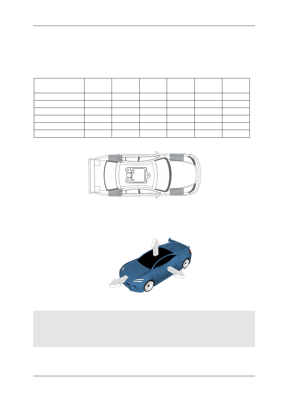
Orientation
The ADR may be installed in one of the 24 possible mounting orientations that align with the primary axes of the
vehicle.
The 24 mounting orientations are defined in the following table.
LEDs face
back
LEDs face
front
LEDs face
up
LEDs face
down
LEDs face
left
LEDs face
right
Connector faces back
X X X X
Connector faces front
X X X X
Connector faces up
X X X X
Connector faces down
X X X X
Connector faces left
X X X X
Connector faces right
X X X X
Figure 8 – Example Mounting Orientation (connector faces back, LEDs face up)
The readings from the three axes of the accelerometer are always aligned to a default vehicle orientation.
+Z
+Y
+X
Figure 9 – Default Vehicle Orientation
Notes:
• All references to the X, Y and Z axes in triggering setup, and logging and CAN outputs, refer to the default vehicle
orientation.
• The installed orientation must be specified using the Device Configuration function; see the
section
on page
.
MoTeC — Published: 11 February 2014
Page 13