Calibration – Bray 6A Series Quick Start User Manual
Page 8
Calibration
Step 13: With the device in ‘AUTO’ mode, test
the responsiveness of the device by varying the
command signal from 4 mA to 20 mA.
Step 14: Upon completion of calibration, insert
an ordinary 4mm wide screwdriver into a slot
located under the adjustment wheel, and move
the wheel to the left until you can feel that it
clicks in. This helps prevent the clutch wheel
from slipping during actuation.
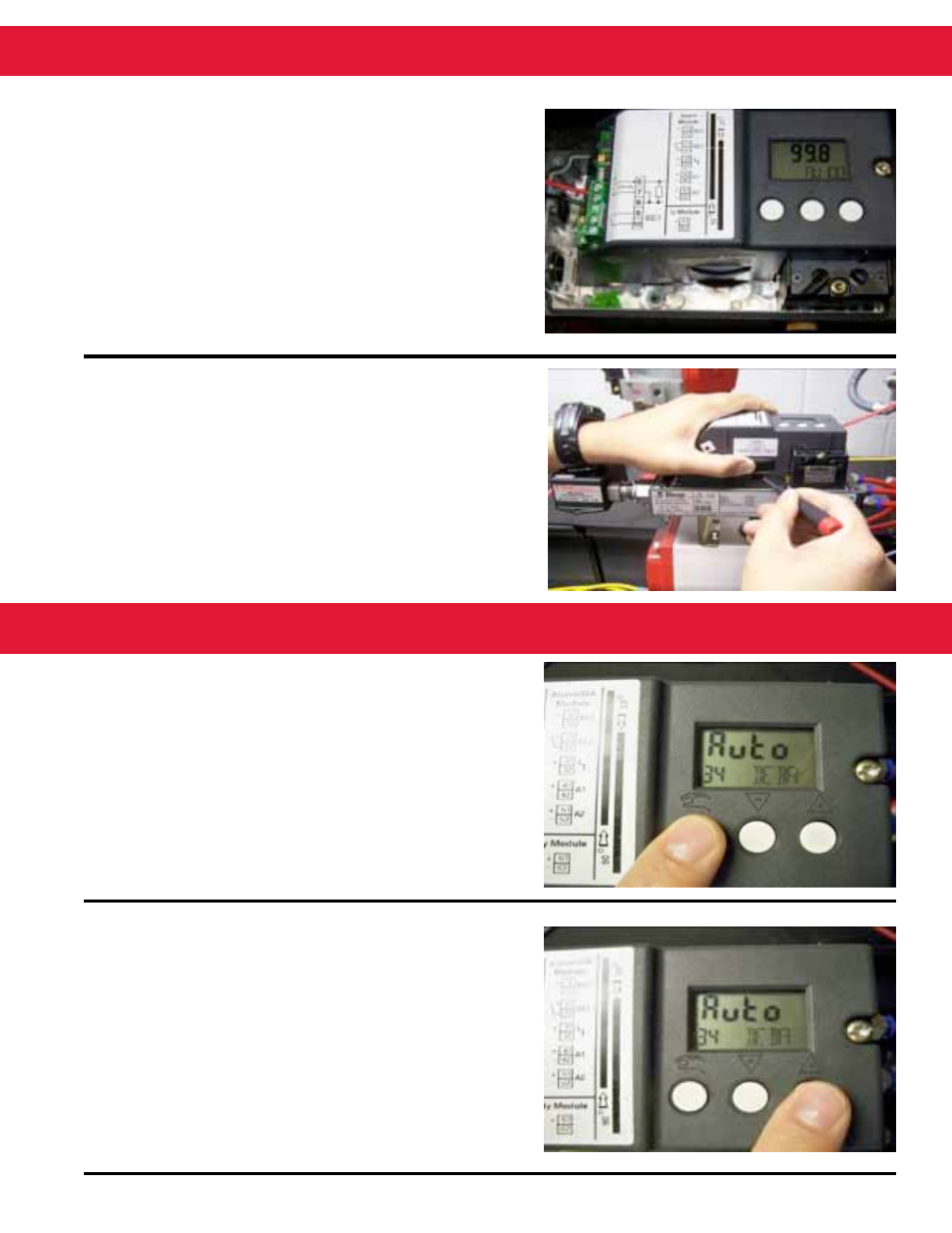
Step 15: While in configuration mode, scroll to
parameter 34 (DEBA).
Step 16: Increase the deadband to yield the
desired responsiveness (recommended value:
1 to 2%) by pressing the ‘+’ button (factory
default is .1%).
To optimize performance, the following measures can be applied if the positioner is too responsive and
does not reach end of travel smoothly.