0 installation, Caution, Table 1 – Bray Triple Offset User Manual
Page 6: Minimum allowable pipe id for tri lok installation
A D i v i s i o n o f B r a y I n t e r n a t i o n a l , I n c .
The Ultimate Critical Service Triple Offset Valve
O p e r a t i o n a n d M a i n t e n a n c e M a n u a l
4
O & M
Notes for Table 1
s
s
s
face of the valve body.
3.0 Installation
1. Tri Lok is designed to be installed between ASME
is open, a portion of the disc may protrude into the
and some gate sizes, the open disc may protrude into
the pipe on the seat side of the valve. Adjacent piping
must be large enough to allow the open disc to clear
the pipe.
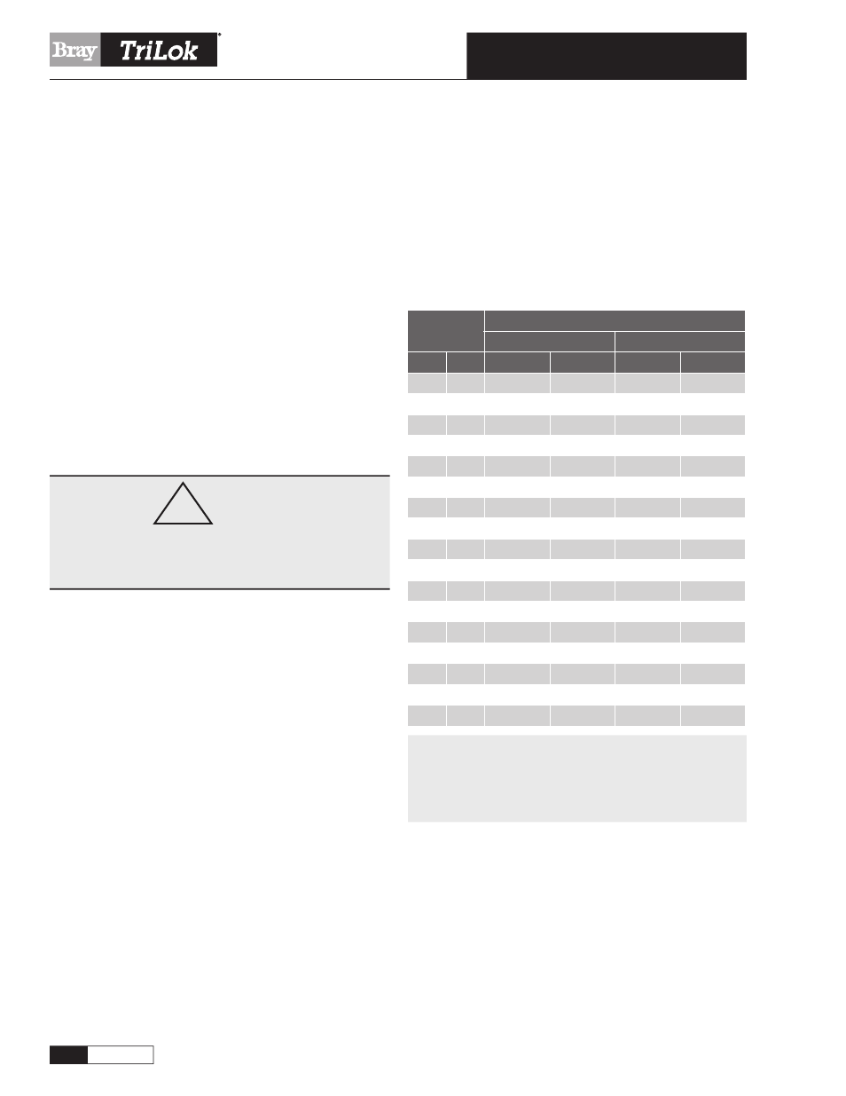
Table 1 shows the minimum allowable pipe ID. In
general, Class 150 valves will clear Schedule 40 pipe,
and Class 300 will clear Schedule 80 pipe without
interference.
2. The valve closes with clockwise rotation of the stem,
and opens with counterclockwise rotation.
!
CAUTION
Avoid uncontrolled rotation of the disc beyond fully-
open position (counterclockwise) as this could damage
the sealing surfaces.
torque and best sealing conditions, install the valve
with the stem on the upstream (pressure side) of the
installation. The valve tag is marked with an arrow
4. Whenever possible, install with the stem in horizontal
position with respect to the ground. If this installation
is not possible, orient the stem at an inclined angle,
with the actuator above the horizontal centerline. This
will prevent debris from accumulating in the bearing
area. With the valve stem horizontal, the weight of
the disc will be supported along the full length of the
bearing journals; thus minimizing operational wear.
5. Flange gaskets should conform to the requirements
of ASME B16.20 (supersedes API Standard 601) for
Flexitallic
®
CG or CGI series, conforming to ASME
B16.20 are recommended.
(
Flexitallic
®
is a registered trademark of The FDS Group)
6. When bolting the valve into the line, use standard
bolting torque as recommended by applicable pip-
ing standards. The valve body seat (replaceable) is
Table 1
Minimum Allowable Pipe ID for Tri Lok Installation
Valve/Pipe
Size
Minimum Pipe ID
Class 150
Class 300
In
mm
In
mm
In
mm
3
80
2.3
51
2.3
51
4
100
3.3
78
3.3
78
6
150
5.3
128
5.1
121
8
200
7.0
172
6.8
165
10
250
8.9
221
8.9
219
12
300
10.9
270
10.9
277
14
350
12.1
300
11.6
294
16
400
14.1
350
13.5
335
18
450
15.9
392
15.3
381
20
500
17.7
450
17.1
427
24
600
21.5
540
21.1
267
30
750
26.9
684
26.7
677
32
800
29.1
740
–
–
36
900
33.1
841
32.6
828
40
1000
36.6
929
–
–
42
1050
38.7
982
37.5
951
48
1200
44.6
1134
43.2
1096