Noise laboratory co., ltd – Atec Noiseken-ESS-200AX User Manual
Page 12
Electrostatic Discharge Simulator
IEC 61000-4-2 standard
EXECUTION OF THE TEST
Direct application of discharges to the EUT
The test voltage shall be increased from the minimum to the
selected test level. The test shall be performed with single
discharges. On selected points at least ten discharges in the
most sensitive polarity shall be applied.
It may be necessary to carry out some investigatory or
preliminary testing to select the points at which discharges
are to be applied. This pretest may be done at a repetition
rate of 20 discharges per second or more.
The ESD gun shall be held perpendicular to the surface to
which the discharge is applied.
In the case of contact discharge, the tip of the discharge
electrode shall touch the EUT before the discharge switch is
operated.
In the case of air discharges, the round tip of the discharge
electrode shall be approached as fast as possible to touch the
EUT. While the discharge electrode approaching, the discharge
switch shall be maintained closed until a discharge occurs.
■
•
Indirect application of the discharge:
Discharges to objects placed or installed near the EUT shall
be simulated by applying the discharges to a coupling plane
in the contact discharge mode.
Horizontal coupling plane: At least 10 single discharges
in the most sensitive polarity shall be applied to the edge
of the plane opposite the center point of the EUT and 0.1m
from the front of the EUT. The ESD gun shall be kept hori-
zontal and perpendicular to the front edge line of the plane.
Vertical coupling plane: At least 10 single discharges in
the most sensitive polarity shall be applied to the center of
one vertical edge of the coupling plane. The coupling plane
shall be placed parallel to, and positioned at a distance of 0.1
m from, the EUT. Discharges shall be applied with suffi cient
different positions such that the four faces of the EUT are
completely iluminated.
•
•
•
ESD GENERATOR SCHEMATIC AND REQUIRED PERFORMANCE
■
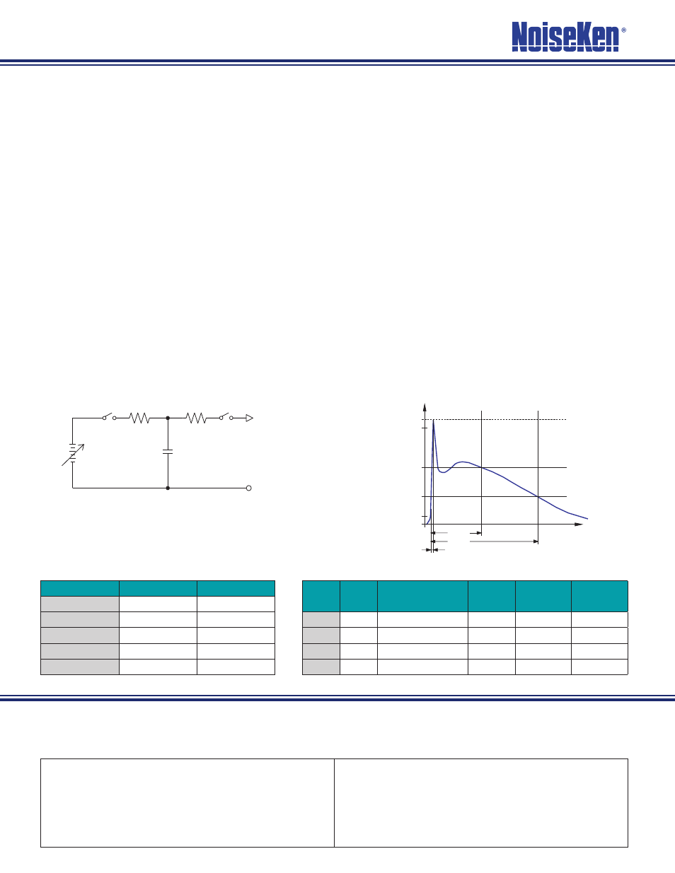
Circuit Diagram
•
ESD typical output waveform
•
Severity Level
•
Waveform parameters
•
Level
Voltage
kV
First peak current
(±10%) lp
Rise time
tr
Current at
30ns (±30%) l
1
Current at
60ns (±30%) l
2
1
2
7.5A
0.7~1ns
4A
2A
2
4
15A
0.7~1ns
8A
4A
3
6
22.5A
0.7~1ns
12A
6A
4
8
30A
0.7~1ns
16A
8A
Level
Contact Discharge Air discharge
1
2 kV
2 kV
2
4 kV
4 kV
3
6 kV
8 kV
4
8 kV
15 kV
X
1)
Special
Special
1)
X is an open level.
Designs and specifi cations are subject to change without notice.
•
http://www.noiseken.com
E-mail: [email protected]
0807-10KⒽ
100%
l
Ipeak
90%
10%
lat30ns
lst60ns
30ns
60ns
tr=0.7 to 1ns
t
l
1
l
2
V
Cs
S
1
Rch
Capacitance Cs: 150pF
Discharge resistance Rd: 330½
Charging resistance Rch: 50-100M½
Output voltage V: Contact 8kV max.
Air 15kV max.
Holding time: at least 5 s
Discharge, mode of operation: Single discharge
(time between successive discharges at least 1 s)
Rd
S
2
NOISE LABORATORY CO., LTD.
1-4-4, Chiyoda, Sagamihara City, Kanagawa Pref., 229-0037 Japan
Tel: +81(0)42-712-2051 Fax: +81(0)42-712-2050
Authorized representative