Operating principle – Atec Rohde-Schwarz-EB500 User Manual
Page 15
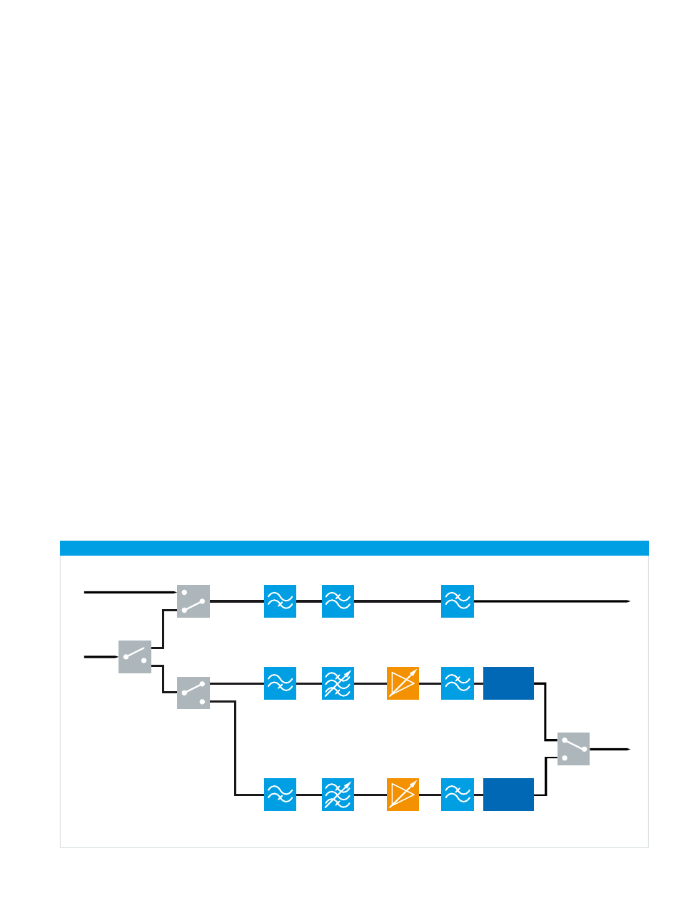
Block diagram of frontend
HF input
to HF
A/D converter
9 kHz to 32 MHz
Lowpass filter
32 MHz
HF preselection filter bank
HF/
VHF/UHF
input
650 MHz to 6 GHz
20 MHz to
650 MHz
Highpass filter
20 MHz
Highpass filter
650 MHz
57.4 MHz
IF3 to
A/D converter
Lowpass filter
8 GHz
Lowpass filter
650 MHz
Variable preamplifier
Variable preamplifier
Preselection
filter bank
Preselection
filter bank
2-stage
super-het
receiver
3-stage
super-het
receiver
Rohde & Schwarz R&S®EB500 Monitoring Receiver 15
via the LAN interface or on the display, results are postpro
cessed using the average, min. hold or max. hold function
as selected by the user.
In the second path, which also includes a DDC and digital
filters, the signal is processed for level measurement or
demodulation. To process the different signals with opti
mum signaltonoise ratio, the receiver contains IF filters
with demodulation bandwidths from 100 Hz to 20 MHz,
which can be selected independently of the spectral IF
bandwidth.
Prior to the level measurement, the absolute value of the
level is determined and weighted using the average, peak,
RMS or fast (sample) function, as selected by the user.
The measured level is then output on the display or via the
LAN interface.
To demodulate analog modulated signals, the complex
baseband data passes through AM, FM, USB, LSB, ISB,
pulse or CW demodulation stages after the bandpass fil
ter and is subjected to automatic gain control (AGC) or
manual gain control (MGC). After the AGC/MGC stage, the
complex baseband data (up to 5 MHz of I/Q data) resulting
from the digitally modulated signals is directly output for
further processing.
The results obtained are available as digital data and can
be output via the LAN interface as required for the particu
lar task. Digital audio data is reconverted to analog signals
for output via the headphone socket or loudspeaker.
Operating principle
Frontend
Signals are fed in via two separate antenna sockets. One
of the sockets can be used for HF signals from 9 kHz to
32 MHz, the other is a combined socket for HF/VHF/UHF
signals from 9 kHz to 6 GHz. A switching system splits
the input signals across three separate signal processing
paths, based on frequency.
Signals from 9 kHz to 32 MHz are routed directly to the
A/D converter via an HF preselection block consisting of a
tunable bandpass filter and a 32 MHz lowpass filter. Sig
nals from 20 MHz to 650 MHz or from 650 MHz to 6 GHz
are routed to the twostage or threestage IF section
through the VHF/UHF preselection and a preamplifier (vari
able gain). The preselection and the low distortion mode
effectively protect the IF sections against overloading.
The two IF sections process the signals from 20 MHz to
6 GHz for the subsequent A/D converter.
Digital signal processing
After A/D conversion of the signal (in each case, with a
16bit converter), the signal path is split up:
In the first path, the IF spectrum is calculated using a digi
tal downconverter (DDC), a digital filter and an FFT block.
The bandwidth of the bandpass filter can be selected be
tween 1 kHz and 20 MHz. Before the IF spectrum is output