40g sdh/sonet sdh/sonet application, Generator – Atec JDSU-ONT Series User Manual
Page 9
ONT-5xx 40/43 Gb/s Test Solution
9
Receiver
Recovered clock output
Via 50
W SMA connector, with clocking at line rate/64
Displays the current optical input level and the min/max values
with timestamp.
Displays the current signal frequency and offset and the min/max
values with timestamp.
Generator
Test pattern
PRBS: 2
31
-1, 2
23
-1, 2
15
-1, 2
11
-1, 2
7
-1,
2
31
-1 inv., 2
23
-1 inv., 2
15
-1 inv., 2
11
-1 inv., 2
7
-1 inv.
(Conforming to ITU-T O.150)
Error insertion
Type
Bit errors
Trigger
Single, rates from 1 x 10
-3
to 1 x 10
-12
With mantissa equal 1
Alarm insertion
Type
LOS
Trigger
Continuous
Trigger output
Type
Off, Laser on
Pulse output
Event present, logical high
Level
TTL compatible, high >2.4 V, low <0.8 V
Connector
BNC, 75 Ω
Analyzer
Analysis of test pattern
PRBS: 2
31
-1, 2
23
-1, 2
15
-1, 2
11
-1, 2
7
-1,
2
31
-1 inv., 2
23
-1 inv., 2
15
-1 inv., 2
11
-1 inv., 2
7
-1 inv.
(Conforming to ITU-T O.150)
Error measurement
Type
Bit errors
Alarm detection
Type
LOS, Pattern Loss
Resolution
100 ms
Result display of errors and alarms
Numerical display
Count, ratio and duration are displayed for each error
Duration is displayed for each alarm
Tabular display
Display of all results with time stamps
Criteria
Start, stop, duration, count
Intermediate bit error
In addition to the long term bit error measurement, intermedi-
ate results are available.
Interval
1 s up to 3600 s,
Results
Current/previous interval,
Count and ratio
Trigger output
Type
Off, LOS alarm
Pulse output
Event present, logical high
Level
TTL compatible, high >2.4 V, low <0.8 V
Connector
BNC, 75 Ω
40G SDH/SONET
SDH/SONET application
SDH/SONET testing
Generation/evaluation of STM-256 signal according to ITU-T G.707
Generation/evaluation of OC-768 signal according to ANSI T1.105
Mapping
SDH
VC-4-256c, VC-4-64c, VC-4-16c, VC-4-4c, VC-4, AU-3/VC-3
SONET
STS-768c SPE, STS-192c SPE, STS-48c SPE,
STS-12c SPE, STS-3c SPE, STS-1 SPE
Generator
Generator modes
Free definable foreground
•
All channels identical
•
Background selectable mapping, depending on foreground chan-
•
nel with definable path overhead and Null pattern as payload
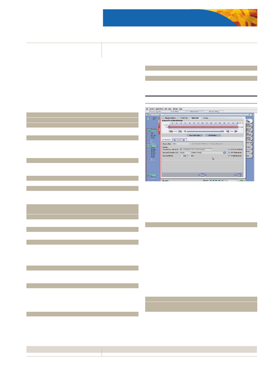
Auto signal structure
Receiver analyses the signal structure (mapping, payload, traces)
automatically for easy configuration of the test channel.
Test pattern
PRBS: 2
31
-1, 2
23
-1, 2
15
-1, 2
11
-1,
2
31
-1 inv., 2
23
-1 inv., 2
15
-1 inv., 2
11
-1 inv.
(Conforming to ITU-T O.150)
Programmable word
Length 32 bits