Atec JDSU-ONT Series User Manual
Page 14
ONT-5xx 40/43 Gb/s Test Solution
14
Stuffing counts
Positive, negative, sum count, duration of affected seconds
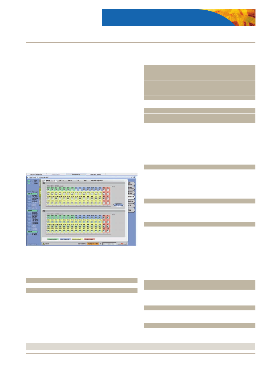
Overhead
Overhead evaluation (frame alignment/OTU/ODU/OPU)
Display of the complete overhead
•
SM TTI, PM TTI, TCM1…6 TTI display of the 64 byte ASCII sequence
•
of SAPI, DAPI and Operator field
One sequence of up to 256 bytes can be captured and displayed
•
for a selectable OH byte
Display payload structure identifier (PSI) bytes, payload type iden-
•
tifier (PT) clear text and support of MSI
Editable PT expectation value as mismatch criterion
•
FTFL forward/backward (FW/BW) fault indication and operator
•
identifier fields
Trace references
Set of SAPI and DAPI expectation values in traces SM TTI, PM TTI,
•
TCM1…6 TTI
Select evaluation type of the received signal: SAPI or DAPI or SAPI/
•
DAPI
General Communication Channel Capture (GCC, in preparation)
The management information between network element and
termination equipment is transported in the GCCs in the OTN
overhead. With this feature, the transmitted information can be
captured in real-time.
Captured fields
GCC0, GCC1, GCC2, GCC1+2
Captured format
Raw
Capture size
up to 500 MB
Trigger
Manual
Error measurement
Validation of data for error measurement occurs after frame ali-
gnment, descrambling, and FEC computation and correction (if
enabled).
Alarm detection
Types
LOF, OOF, LOM, OOM
OTU-AIS, ODU-AIS, ODU-OCI, ODU-LCK, SM BDI, SM IAE, SM
BIAE, SM TIM, PM-BDI, PM TIM
FW-SD, FW-SF, BW-SD, BW-SF
TCMi-LTC, TCMi-BDI, TCMi-IAE, TCMi-BIAE, TCMi-TIM (i = 1 to 6)
CL-LOSS (Client signal loss of synchronization)
PT-MISM
Error detection
Types
FAS, MFAS, SM BIP, SM BEI, PM BIP, PM BEI
TCMi BIP, TCMi BEI (i = 1 to 6)
Bit error (only available for PRBS/digital word testing signal)
Resolution
100 ms
Result display of errors and alarms
Numerical display
Count, ratio and duration are displayed for each error
Duration is displayed for each alarm
Tabular display
Display of all results with time stamps
Criteria
Start, stop, duration, count
Graphical display
Display of all events as bar graphs versus time. Cursors allow easy
identification and zooming (in and out) on results. Filters enable
event selection.
Time axis
Second, minute, hour
Intermediate bit error
In addition to the long term bit error measurement, intermedi-
ate results are available.
Interval
1 s up to 3600 s,
Results
Current/previous interval,
Count and ratio
OTU FEC
The FEC analysis and correction can be switched on and off. Using
the OTU FEC field, FEC according to the Reed-Solomon (255,239)
algorithm is performed on the received frame. With data blocks
consisting of 239 data bytes and 16 FEC field bytes, up to 16 byte
errors can be detected or 8 byte errors be corrected.
Error detection
Type
FECcorrectable bit, FECcorrectable code word,
FECuncorrectable code word
Result display of errors
Numerical display
Count, ratio and duration are displayed for each error
Tabular display
Display of all results with time stamps
Criteria
Start, stop, duration, count