Atec JDSU-JD720C Series User Manual
Jd72oc-series, Cable and antenna analyzers
website
:
www.jdsu.com/test
COMMUNICATIONS TeST & MeASUreMeNT SOlUTIONS
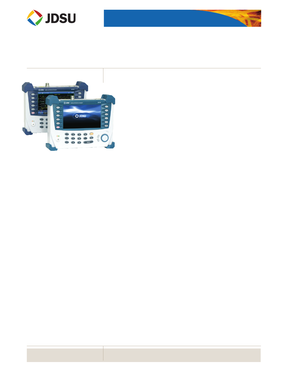
JD72OC-Series
Cable and Antenna Analyzers
Key Benefits
• Intuitive user interface with touch screen and indoor/outdoor
display modes
• Dual display and zoom zones for faster analysis
• RF port protection up to 40 dBm (10 W)
• Controls RF and optical power sensors
Key Features
• Favorite and Quick Save keys for
easier and faster testing
• Broadband calibration for
maximum test time
• 7.5 hours of continuous battery
operation
Applications
• Trace overlay
• Zoom zones
• Dual display
• Alternate sweep in DTF
Key Measurements
• Reflection — VSWR/return loss
• DTF — VSWR/return loss
• 1-Port cable loss
• Smith chart
• 1-Port phase
• RF power meter (optional)
• Optical power meter (optional)
The majority of problems in mobile networks occur in the base station’s infrastruc-
ture, consisting of the antenna system, cables, and connectors. To properly service
and install cell sites requires suitable test equipment. The JDSU JD720C-Series
Cable and Antenna Analyzers are optimal test solutions for characterizing cell-site
infrastructure because of their handheld design, ease of use, and rich functionality.
The JD720C-series analyzers offer the measurement functions necessary to accu-
rately verify a site’s transmission line and antenna system from signal reflections
(voltage standing wave ratio [VSWR] or return loss) to RF or optical transmission
power.
In addition, the JD720C-series analyzers accurately measure the distance to fault
(DTF) for proper identification of its location.
The instrument’s touch-panel operation and 7-inch-wide thin-film transistor
(TFT) color display for easier measurements and display. Also, its application-spe-
cific software for easier measurement comparison and analysis and for generating
professional reports.