Atec Anritsu-MG3690B User Manual
Page 14
14
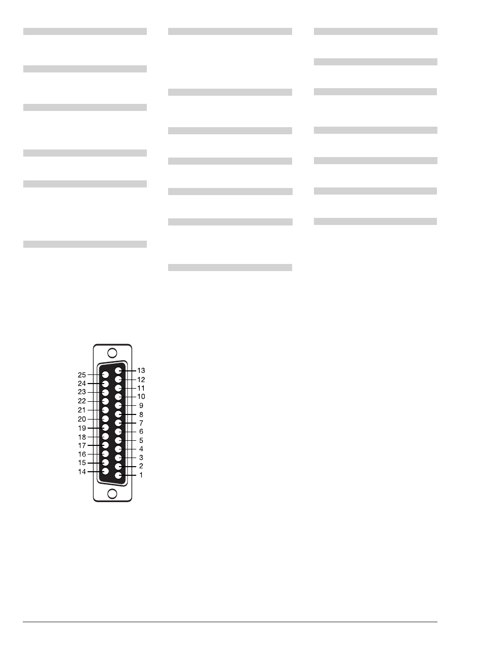
AUX I/O (Auxiliary Input/Output)
Provides for most of the rear panel BNC connections
through a single, 25-pin, D type connector. Supports
master-slave operation with another synthesizer or
allows for a single-cable interface with the Model
56100A Scalar Network Analyzer and other Anritsu
instruments. (see figure below)
SERIAL I/O (Serial Input/Output)
Provides access to RS-232 terminal ports to support
service and calibration functions and master-slave
operations.
IEEE-488 GPIB
Provides input/output connections for the
General Purpose Interface Bus (GPIB).
mmW BIAS
Provides the bias for the external waveguide multipliers
for coverage up to 325 GHz.
RF, LO, IF
Provides access to an internal IF up-conversion mixer,
Option 7.
PULSE TRIG IN
Accepts an external TTL compatible signal to pulse
modulate the RF output signal or to trigger or to gate
the optional internal pulse generator. Available with
Option 26, Pulse Modulation.
PULSE SYNC OUT
Provides a TTL compatible signal, synchronized to the
internal pulse modulation output, Option 27.
EXT ALC IN
Provides for leveling the RF output signal externally with
either a detector or power meter. Signal requirements
are shown in the RF Output specifications.
RF OUTPUT
Provides for RF output from 50Ω source impedance.
K Connector, female. Option 9 moves the RF Output
connector to the rear panel.
10 MHz REF IN
Accepts an external 10 MHz ±100 Hz, 0 to +20 dBm
time-base signal. Automatically disconnects the
internal high-stability time-base option, if installed.
50Ω impedance.
10 MHz REF OUT
Provides a 1Vp-p, AC coupled, 10 MHz signal derived
from the internal frequency standard. 50Ω impedance.
HORIZ OUT (Horizontal Sweep Output)
Provides 0V at beginning and +10V at end of sweep,
regardless of sweep width. In CW mode, the voltage
is proportional to frequency between 0V at low end
and +10V at the high end of range. In CW mode, if
CW RAMP is enabled, a repetitive, 0V to +10V ramp
is provided.
EFC IN
Provides the capability to frequency modulate the
internal crystal oscillator, allowing phase locking the
synthesizer inside an external lock loop. Specifications
on page 2.
PULSE VIDEO OUT
Provides a video modulating signal from the internal
pulse generator, Option 27.
AM IN
Accepts an external signal to amplitude modulate the
RF output signal, Option 14. 50Ω impedance.
FM/ΦM IN
Accepts an external signal to frequency or phase
modulate the RF output signal, Option 12.
50Ω impedance.
AM OUT
Provides the amplitude modulation waveform from the
internal LF generator, Option 27.
FM/ΦM OUT
Provides the frequency or phase modulation waveform
from the internal LF generator, Option 27.
SCAN MOD IN
Accepts an external signal to scan modulate the
RF output signal, Option 20. High Impedance.
POWER MONITOR IN
Accepts an external detector for power monitoring,
Option 8.
Aux I/O pins:
1. Horizontal Output
2. Chassis Ground
3. Sequential Sync Output
4. Low Alternate Enable Output
5. Marker Output
6. Retrace Blanking Output
7. Low Alternate Sweep Output
8. Chassis Ground
9. -
10. Sweep Dwell Output
11. Lock Status Output
12. Penlift
13. External Trigger Input
14. V/GHz Output
15. End-of-Sweep Input
16. End-of-Sweep Output
17. -
18. Sweep Dwell Input
19. -
20. Bandswitch Blanking Output
21. Master Reset
22. Horizontal Sweep Input
23. Horizontal Sweep Input Return
24. Chassis Ground
25. Memory Sequencing Input
25-pin, D type connector