General specifications – Atec Chroma-62000P Series User Manual
Page 6
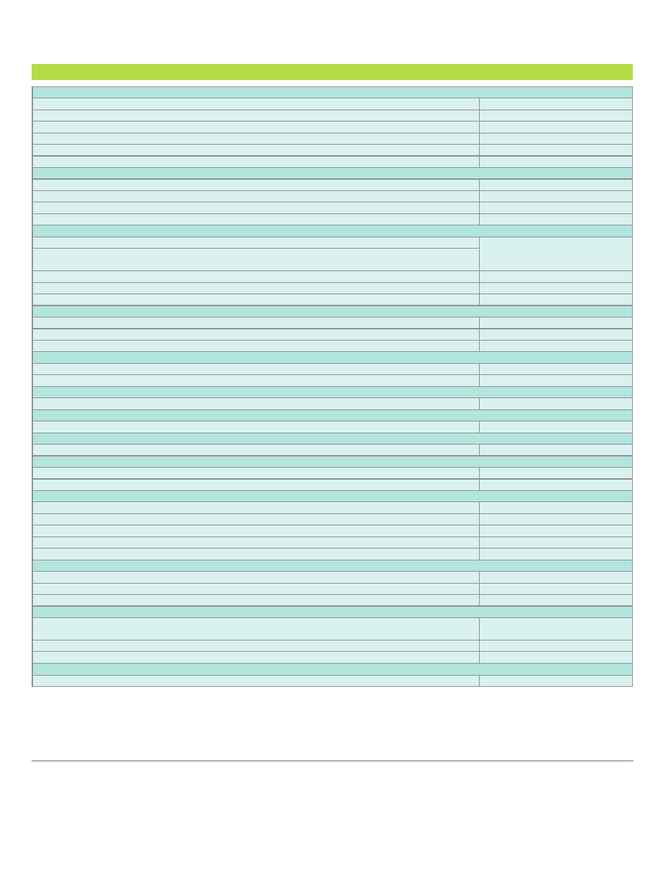
Programming & Measurement Resolution
Voltage (Front Panel)
10 mV
Current (Front Panel)
10 mA
Voltage (Remote Interface)
0.003% of Vmax
Current (Remote Interface)
0.002% of Imax
Voltage (Analog Programming Interface )
0.04% of Vmax
Current (Analog Programming Interface )
0.04% of Imax
Programming Accuracy
Voltage Programming (Front Panel and Remote Interface )
0.1% of Vmax
Voltage Programming (Analog Programming Interface )
0.2% of Vmax
Current Programming (Front Panel and Remote Interface )
0.3% of Imax
Current Programming (Analog Programming Interface )
0.3% of Imax
Programming Response Time
Rise Time : For a programmed 5% to 95% step in output voltage.(Full & No Load)
See Electrical Specification
Fall Time : For a programmed 95% to 5% step in output voltage.
(The fall time will be affected by the external loading from UUT.)
Vout setting (USB send command to DC source receiver)
10ms
Measure Volt , Current (under USB command using Fetch)
10ms
Measure Volt , Current (under USB command using Measure)
70ms
Analog Programming Interface
Voltage and Current Programming inputs
0~10Vdc or 0~5Vdc of F.S.
Voltage and Current monitor
0~10Vdc or 0~5Vdc of F.S.
Isolation : Maximum working voltage of any analog programming signal with respect to chassis potential.
70Vdc
Auxiliary Power Supply
Output Voltage
12Vdc
Maximum Current Source Capability
10mA
Remote inhibit function (I/O)
Use to disable the output of DC power supply; Active Low
TTL
DC-ON Output Signal
Indicate the output status; Active High
TTL
Fault output signal
Indicate if there is a fault/protection occurred; Active Low
TTL
Series & Parallel operation function with Master / Slave control
Voltage limit @ Series Mode
See Electrical Specification
Number of DC Power Supplies allowed @ Master / Slave control mode
5
Auto Sequencing Programmable Function
Number of program
10
Number of sequence
100
Time Range
5ms - 15,000S
TTL signal out
8 bits
TTL source capability
7 mA
Voltage Step Mode Programmable Function
Start Voltage Range
0~full scale
End Voltage Range
0~full scale
Total Run Time Range (hhh:mm:ss.sss)
10ms - 99 hours
Slew Rate Control Function
Voltage slew rate range
(The fall slew rate will be affected by the discharge rate of the output capacitors especially under no load condition.)
See Electrical Specification
Current slew rate range
See Electrical Specification
Minimum transition time.
0.5 ms
Remote Sense
Line loss compensation
5V
GENERAL SPECIFICATIONS
All specifications are subject to change without notice. Please visit our website for the most up to date specifications.
62000P-E-201207-2000
Worldwide Distribution
and Service Network
JAPAN
CHROMA JAPAN CORP.
472 Nippa-cho, Kouhoku-ku,
Yokohama-shi, Kanagawa,
223-0057 Japan
http://www.chroma.co.jp
E-mail: [email protected]
U.S.A.
CHROMA SYSTEMS
SOLUTIONS, INC.
25612 Commercentre Drive,
Lake Forest, CA 92630-8830
Tel: +1-949-600-6400
Fax: +1-949-600-6401
Toll Free: +1-866-600-6050
http://www.chromausa.com
E-mail: [email protected]
Developed and Manufactured by :
CHROMA ATE INC.
致茂電子股份有限公司
HEADQUARTERS
66 Hwaya 1st Rd., Kueishan
Hwaya Technology Park,
Taoyuan County 33383,
Taiwan
Tel: +886-3-327-9999
Fax: +886-3-327-8898
http://www.chromaate.com
E-mail: [email protected]
EUROPE
CHROMA ATE EUROPE B.V.
Morsestraat 32, 6716 AH Ede,
The Netherlands
Tel: +31-318-648282
Fax: +31-318-648288
http://www.chromaeu.com
E-mail: [email protected]
CHINA
CHROMA ELECTRONICS
(SHENZHEN) CO., LTD.
8F, No.4, Nanyou Tian An
Industrial Estate, Shenzhen,
China PC: 518052
Tel: +86-755-2664-4598
Fax: +86-755-2641-9620