Atec Chroma-62000P Series User Manual
Page 3
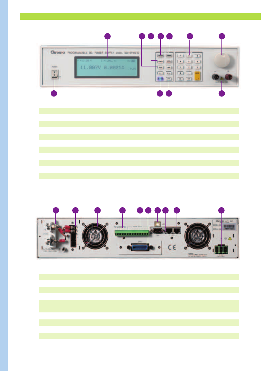
PANEL DESCRIPTION
1
2
3
7
6
5
4
8
9 10
11
12
19
18
17
16
15
14
13
20
1. LCD Display
Display setting, readings and operating status
2. PROG Key
Program the sequence
3. CONFIG Key
Set the system configuration
4. VOLTAGE Key
Set the output voltage
5. CURRENT Key
Set the output current limit
6. NUMERIC Key
Set the data
7. ROTARY Key
Adjust the V&I and set the parameter
8. POWER Switch
9. OUTPUT Key
Enable or disable the output
10. LOCK Key
Lock all settings
11. OUTPUT Terminal
Connect the output cable to a UUT
Note : 40V, 300V & 600V Model have no output terminal at the front panel.
Model : 62012P-80-60
Model : 62012P-80-60
21
12. OUTPUT Terminal
Connect the output cable to a UUT
13. Sense Terminal
Connect the UUT for voltage compensation
14. System Fan
15. Analog programming interface
For analog level to program and monitor output voltage & current
16. System I/O port
Send 8 bit TTL, DC-ON, fault output signal and remote inhibit
and trigger input signal
17. GPIB Connector(Optional)
GPIB & Ethernet (alternative)
18. RS-232 Connector
19. RS-485 Connector
For master/slave control
20. AC Input Terminal
21. USB Connector