Bts master™ base station analyzer features, Td-scdma/hsdpa signal analyzers – Atec Anritsu-MT8221B User Manual
Page 16
16
BTS Master™ Base Station Analyzer Features
TD-SCDMA/HSDPA Signal Analyzers
(Options 0060, 0061, 0038)
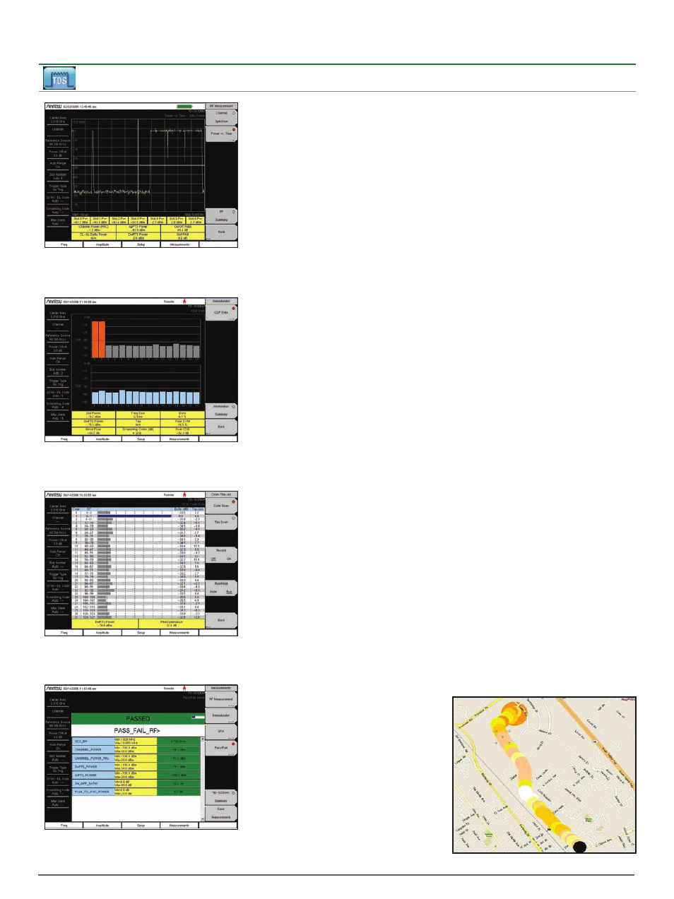
RF Measurement – Time Slot Power
Empty downlink slots with access power will reduce the
sensibility of the receiver and the size of the sector.
This will cause dropped and blocked calls.
Demodulation – Scrambling Code
Scrambling Code measurements provide a check for
the BTS settings. Scrambling Code errors can cause a
very high dropped call rate on hand off.
Over-the-Air Measurements – Code Scanner
Excessive sync codes produce too much co-channel
interference, which leads to lower capacity, low data
rate and excessive handoffs.
Pass/Fail Test
Set up common test limits, or sets of limits, for
each instrument. Inconsistent settings between base
stations, leads to inconsistent network behavior.
RF Measurements
(Option 0060)
Channel Spectrum
Channel Power
Occupied Bandwidth
Left Channel Power
Left Channel Occ B/W
Right Channel Power
Right Channel Occ B/W
Power vs. Time
Six Slot Powers
Channel Power (RRC)
DL-UL Delta Power
UpPTS Power
DwPTS Power
On/Off Ratio
Slot Peak-to-Average Power
Spectral Emission
Demodulation
(Option 0061)
Code Domain Power/Error
(QPSK/8 PSK/16 QAM)
Slot Power
DwPTS Power
Noise Floor
Frequency Error
Tau
Scrambling Code
EVM
Peak EVM
Peak Code Domain Error
Over-the-Air (OTA) Measurements
(Option 0038)
Code Scan (32)
Scrambling Code Group
Tau
E
c
/I
o
DwPTS Power
Pilot Dominance
Tau Scan (Six)
Sync-DL#
Tau
E
c
/I
o
DwPTS Power
Pilot Dominance
Auto-Save with GPS Tagging and Logging
TD-SCDMA/HSDPA Signal Analyzers
The BTS Master features three TD-SCDMA/
HSDPA measurement modes:
• RF Measurements
• Demodulation
• Over-the Air Measurements (OTA)
The goal of these measurements is
to increase data rate and capacity by
accurate power settings, ensuring low
out-of-channel emissions, and good signal
quality. These attributes help to create a
low dropped call rate, a low blocked call
rate, and a good customer experience.
Cell site technicians or RF engineers can
make measurements Over-the-Air (OTA)
to spot-check a transmitter’s coverage
and signal quality without taking the cell
site off-line. When the OTA test results are
ambiguous one can directly connect to the
base station to check the signal quality
and transmitter power.
Error Vector Magnitude (EVM) EVM is the
ratio of errors, or distortions, in the actual
signal, compared to a perfect signal. EVM
faults will result in poor signal quality to
all user equipment. In turn, this will result
in extended hand off time, lower sector
capacity, and lower data rates, increasing
dropped and blocked calls.
Peak Code Domain Error (Peak CDE)
Peak CDE is the EVM of the worst code.
Code Domain displays show the traffic
in a specific time slot. Peak CDE faults
will result in poor signal quality to all
user equipment. In turn, this will result
in extended hand off time, lower sector
capacity, and lower data rates.
OTA Tau Scanner E
c
/I
o
E
c
/I
o
faults indicate excessive or
inadequate coverage and lead to low
capacity, low data rates, extended
handoffs, and excessive call drops.
DwPTS OTA Power Mapping
DwPTS OTA Power when added to
E
c
/I
o
gives the absolute sync code power
which is often proportional to PCCPCH
(pilot) power. Use this to check and plot
coverage with GPS. Coverage plots can
be downloaded to PC based mapping
programs for later analysis. Poor readings
will lead to low capacity, low data rates,
excessive call drops and call blocking.