7 power up and test – Alpha Technologies APB HFC Voltage Booster User Manual
Page 17
17
016-559-B0-001 Rev. A
2.0 Installation,
continued
2.7 Power Up and Test
2.7.1 Initial Power Up
Tools Required:
•
True RMS Volt Meter
• Clamp-On
Amp
Meter
Procedure:
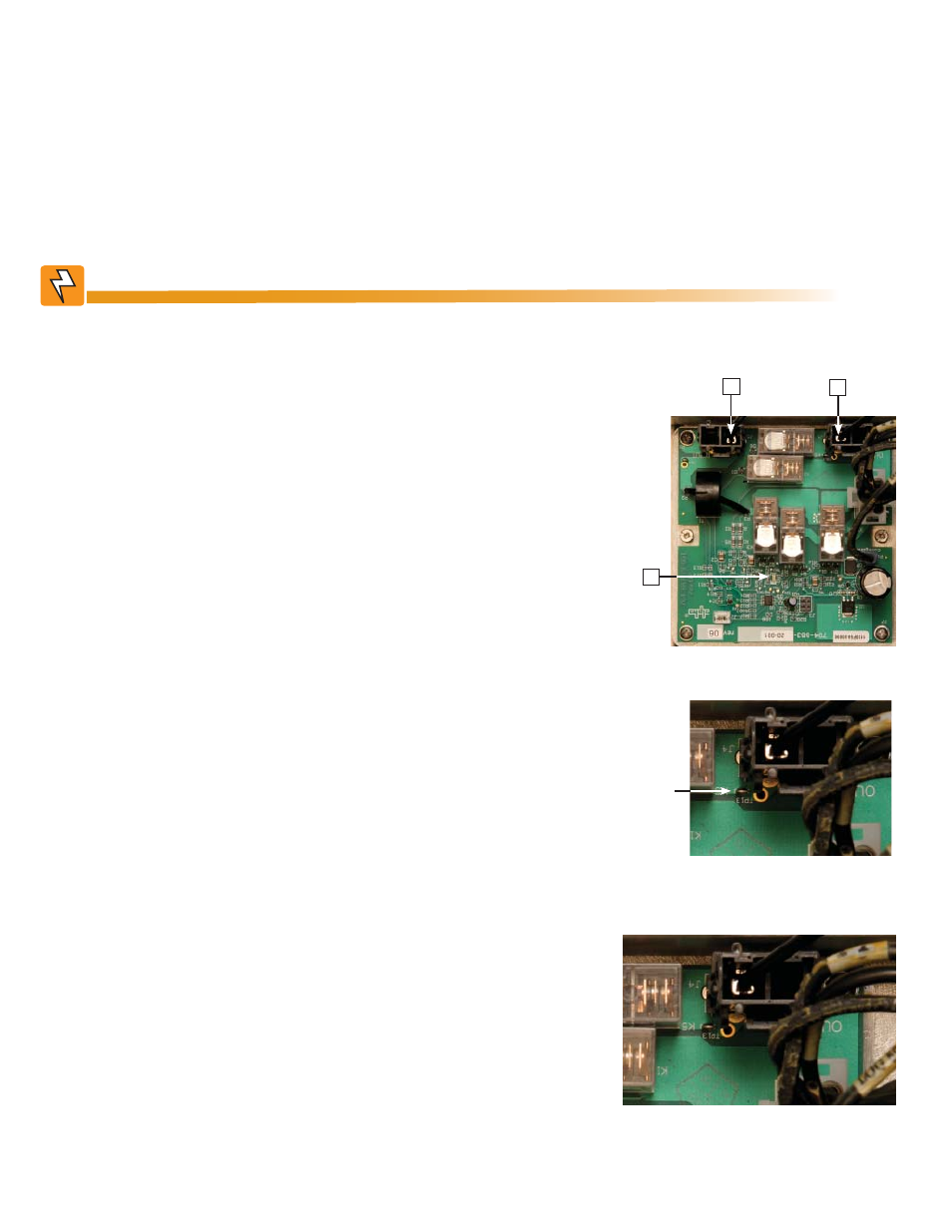
1. Plug the Output Connector from the RF Module
into the J4 Output Connector (item 1) of the PCB.
2. Plug the Input Connector from the RF Module into
the J5 Input Connector (item 2) of the PCB. Verify
the GREEN LED (item 3) on PCB is lit.
4. Place a Clamp-on amp meter over the output wire
coming from the Output connector J4 on the PCB
and the RF Module. The current must be less than
8A RMS. If the current exceeds 8A RMS, resolve
the cause of the short-circuit or overload condition.
3. Using the volt meter, measure the output voltage
between TP13 and the enclosure chassis. The
voltage should be approximately 87Vac for the
87Vac confi guration or 63Vac for the 63Vac
confi guration.
There will be up to 90Vac present on the PCB when a live connector is plugged into the
input or output connectors.
WARNING!
2
1
TP13
3
- AlphaCell GelCell Series (32 pages)
- FXM 650, 1100, 2000 UPS (96 pages)
- Cordex 48-1.2kW (68 pages)
- Radium MiniBay (57 pages)
- Fiber Backhaul Enclosure (FBE) (19 pages)
- FBE2322 Enclosure System (38 pages)
- FlexNet PMR, GMR Series (49 pages)
- Te25xh (38 pages)
- FlexNet MPS48-12M - Technical Manual (33 pages)
- FlexNet MPS48-12M - Quick Start Guide (2 pages)
- FlexNet ELPM 300-48D (25 pages)
- FlexNet FMPS (40 pages)
- FlexPoint AX Series (34 pages)
- FlexPoint FPR1207-F - Technical Manual (18 pages)
- FlexPoint FPR1207-F - Quick Start Guide (2 pages)
- AlphaGen PN-6x-T 7.5kW 48VDC - Installation and Operation Manual (79 pages)
- AlphaGen CE-3x2 5K-T 48Vdc (95 pages)
- AlphaGen PN-6x-T 7.5kW 48Vdc (95 pages)
- AlphaGen 3.5_5.0kW Kohler COM5 (80 pages)
- Security Bar Field For UPE-3, UPE-6, UPE-M3, UPE-M6, PN Series and CE Series (2 pages)
- AMPS80 HP (116 pages)
- 255A Bypass Switch (24 pages)
- AMP24 HP (108 pages)
- FXM350_Micro350 UPS (112 pages)
- CFR 600, CFR 600XT, CFR 1000 (70 pages)
- BPS Series Bypass Switch (36 pages)
- CFR Intelligent Interface Device (54 pages)
- CFR Redundant Control Unit (23 pages)
- CFR 5000, CFR 5000RM (88 pages)
- CFR 3000, CFR 3000RM (86 pages)
- CFR 1500, CFR 1500RM (83 pages)
- CFR 1500, CFR 2000, CFR 2500, CFR 3000 (76 pages)
- Continuity: 1000_2000_3000 (48 pages)
- Continuity Battery Pack (20 pages)
- Continuity: 6K_10K (52 pages)
- Micro, Micro XL, Micro XL3 UPS (99 pages)
- Micro Secure UPS (80 pages)
- Te17 (32 pages)
- Te45 (68 pages)
- Te41, 48V (76 pages)
- Te41, 24V (72 pages)
- Te43 (60 pages)
- AlphaGuard AG-CMT Installation (2 pages)
- AlphaGuard AG-CMT-3SC_4SC-P (2 pages)
- Digital Midtron DM-3200 AT (2 pages)