2 connecting the service power inserter (spi) – Alpha Technologies PME Series User Manual
Page 36
031-161-B0-006, Rev. F
36
Disconnect all power sources from the SPI (Service Power Inserter) before removing its
cover. Verify that the SPI is disconnected from both the utility power and the power supply
before beginning procedure.
WARNING!
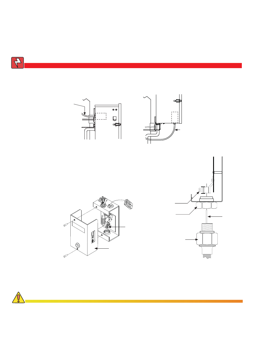
Fig. 2-20, SPI Locations
PME Enclosures
SPI
Power Suppy Output
(Coaxial Cable)
PWE Enclosures
SPI
Power Suppy Output
(Coaxial Cable)
Procedure:
1. Disconnect the SPI from all power sources.
2. Remove the two screws securing the cover to the SPI chassis.
Remove the cover, exposing the circuit board and seizure
screw assembly.
SPI Cover
Seizure Screw
Assembly
3. Screw the Coaxial Termination into Output Port on bottom of SPI, inserting the stinger
into the seizure screw assembly.
4. Tighten seizure screw to 35 in-lbs.
5. Replace SPI cover and reinstall screws.
6. Verify switch on top of SPI is on the ON position.
Fig. 2-21, SPI
Fig. 2-22, SPI (side view)
Seizure Screw
Stinger
Coaxial
Termination
Output Port
To prevent arcing and failure of the unit, insert the coaxial cable completely into the seizure screw
assembly and tightened the seizure screw to 35 inch-pounds.
CAUTION!
2.0 Installation,
continued
2.4
Connecting the Coaxial Cable, continued
2.4.2 Connecting the Service Power Inserter (SPI)