Alpha Technologies PME Series User Manual
Page 30
031-161-B0-006, Rev. F
30
2.0 Installation,
continued
2.3
Connecting Utility Power, continued
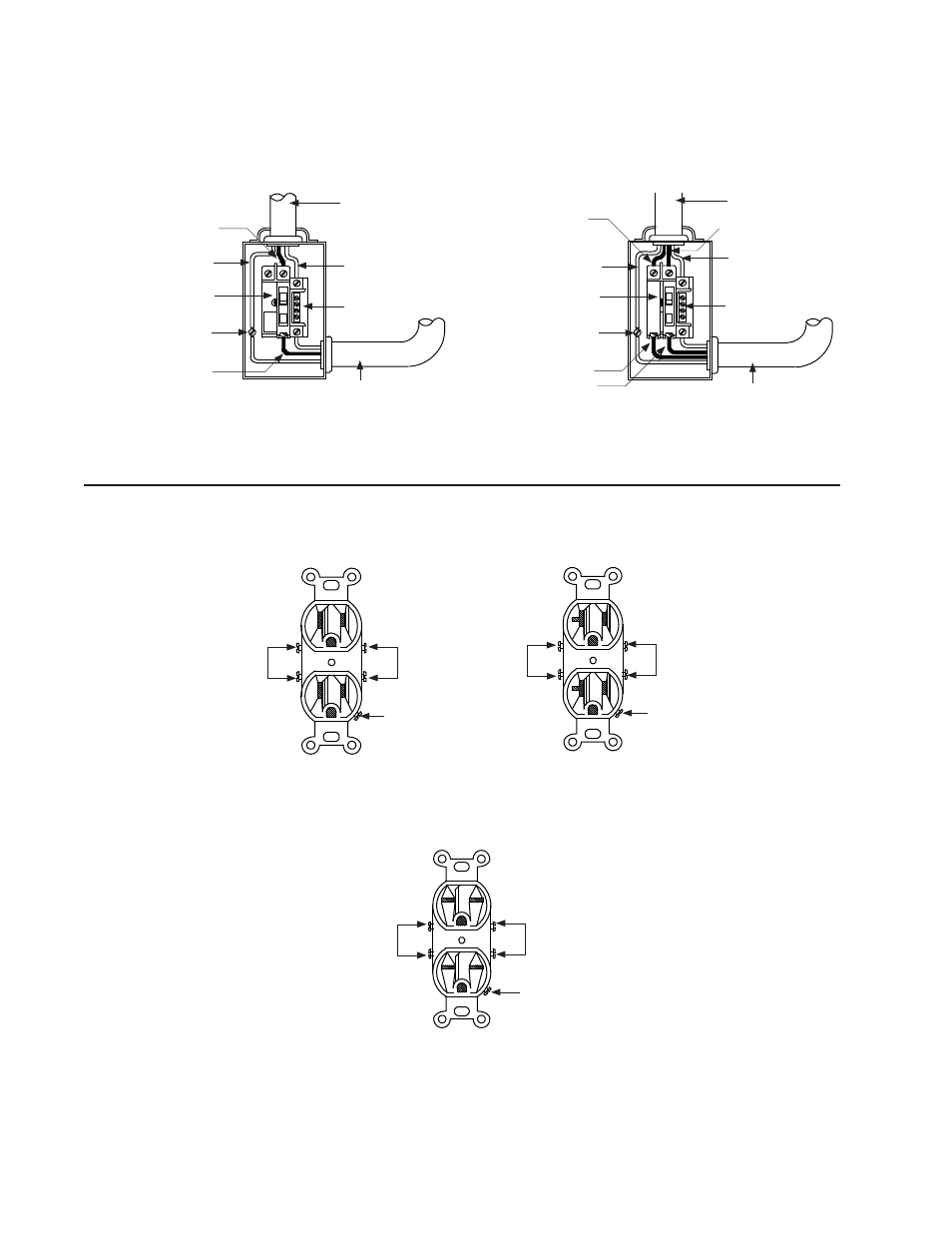
Fig. 2-12, Typical Service Entrance Wiring
L1
(Black)
L1
(Black)
Neutral
(White)
Neutral
(White)
Ground
(Green)
Ground
(Green)
L1
(Black)
L2
(Red)
Ground
(Green)
120Vac 15A Receptacle, 5-15R
120Vac 20A Receptacle, 5-20R
240Vac 15A Receptacle, 6-15R
Fig. 2-13, Typical Receptacle Wiring
L1 (Black)
Copper Ground
Wire #8 AWG min.
Breaker
Grounding Point Made
to Enclosure Wall
L1 (Black)
To Utility
Neutral (White)
Neutral Bus
To Enclosure
Receptacle
120Vac
To Utility
Neutral (White)
Neutral Bus
To Enclosure
Receptacle
L1 (Black)
L2 (Red)
Copper Ground
Wire #8 AWG min.
Breaker
Grounding Point Made
to Enclosure Wall
L1
L2
240Vac
This manual is related to the following products:
See also other documents in the category Alpha Technologies Equipment:
- AlphaCell GelCell Series (32 pages)
- FXM 650, 1100, 2000 UPS (96 pages)
- Cordex 48-1.2kW (68 pages)
- Radium MiniBay (57 pages)
- Fiber Backhaul Enclosure (FBE) (19 pages)
- FBE2322 Enclosure System (38 pages)
- FlexNet PMR, GMR Series (49 pages)
- Te25xh (38 pages)
- FlexNet MPS48-12M - Technical Manual (33 pages)
- FlexNet MPS48-12M - Quick Start Guide (2 pages)
- FlexNet ELPM 300-48D (25 pages)
- FlexNet FMPS (40 pages)
- FlexPoint AX Series (34 pages)
- FlexPoint FPR1207-F - Technical Manual (18 pages)
- FlexPoint FPR1207-F - Quick Start Guide (2 pages)
- AlphaGen PN-6x-T 7.5kW 48VDC - Installation and Operation Manual (79 pages)
- AlphaGen CE-3x2 5K-T 48Vdc (95 pages)
- AlphaGen PN-6x-T 7.5kW 48Vdc (95 pages)
- AlphaGen 3.5_5.0kW Kohler COM5 (80 pages)
- Security Bar Field For UPE-3, UPE-6, UPE-M3, UPE-M6, PN Series and CE Series (2 pages)
- AMPS80 HP (116 pages)
- 255A Bypass Switch (24 pages)
- AMP24 HP (108 pages)
- FXM350_Micro350 UPS (112 pages)
- CFR 600, CFR 600XT, CFR 1000 (70 pages)
- BPS Series Bypass Switch (36 pages)
- CFR Intelligent Interface Device (54 pages)
- CFR Redundant Control Unit (23 pages)
- CFR 5000, CFR 5000RM (88 pages)
- CFR 3000, CFR 3000RM (86 pages)
- CFR 1500, CFR 1500RM (83 pages)
- CFR 1500, CFR 2000, CFR 2500, CFR 3000 (76 pages)
- Continuity: 1000_2000_3000 (48 pages)
- Continuity Battery Pack (20 pages)
- Continuity: 6K_10K (52 pages)
- Micro, Micro XL, Micro XL3 UPS (99 pages)
- Micro Secure UPS (80 pages)
- Te17 (32 pages)
- Te45 (68 pages)
- Te41, 48V (76 pages)
- Te41, 24V (72 pages)
- Te43 (60 pages)
- AlphaGuard AG-CMT Installation (2 pages)
- AlphaGuard AG-CMT-3SC_4SC-P (2 pages)
- Digital Midtron DM-3200 AT (2 pages)