Alpha Technologies CFR Intelligent Interface Device User Manual
Page 18
Maintenance Parameters
"MAINTENANCE PARAMETERS" allow you to customize UPS
detection and warning characteristics. Normally, there should be no need to
change these factory settings. Once the correct security code has been
entered, the fields can be altered by using the < arrow to decrease the
setting, or the > arrow to increase the setting. The bar type display is
arranged for a total of 16 different setting levels, and can be set for any value
between 1 and 16. If a setting is changed, it can easily be reset to the factory
default by placing the cursor over the special character in the bar type chart
and pressing ENTER.
Fast Detect Lo Ref
Changing this value will alter the characteristics of how the UPS
responds to a fast, low amplitude line disturbance (glitch).
Fast Detect Hi Ref
Changing this value will alter the characteristics of how the UPS
responds to a fast, high amplitude line disturbance (spike).
Medium Detect Lo Ref
Changing this value will alter the characteristics of how the UPS
responds to a slow, low amplitude line disturbance (sag).
Medium Detect Hi Ref
Changing this value will alter the characteristics of how the UPS
responds to a slow, high amplitude line disturbance (surge).
Slow Detect Lo Ref
Changing this value will alter the characteristics of how the UPS
responds to a slow, low amplitude line disturbance (brownout).
Slow Detect Hi Ref
Changing this value will alter the characteristics of how the UPS
responds to a slow, high amplitude line disturbance (high brownout or
sustained overvoltage).
Slow Detect Hys Lo Ref
Changing this value will alter the characteristics of the voltage level at
which the UPS will resume LINE POWER operation after a brownout
condition has been corrected.
Slow Detect Hys Hi Ref
Changing this value will alter the characteristics of the voltage level at
which the UPS will resume LINE POWER operation after an overvoltage
condition has been corrected.
3. OPERATION
2. INSTALLATION
11
11
11
11
11
30
7
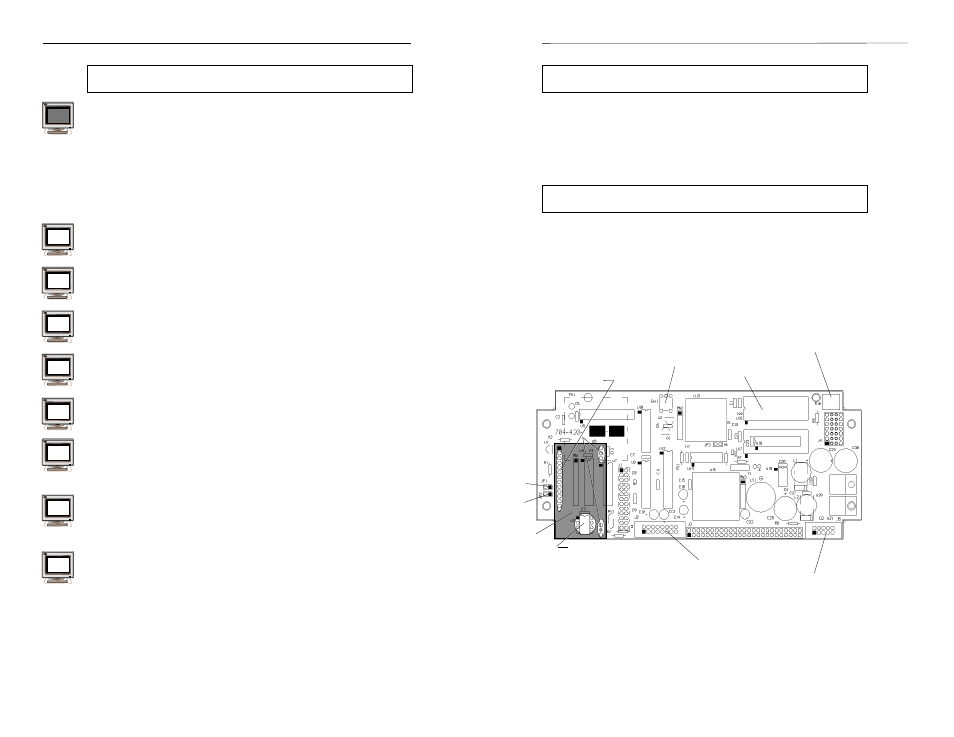
Contrast Adjustment
If the display appears either too dark, (dark blocks are displayed along
with the text), or too light, (no text displayed), carefully remove the front panel
as previously described. Locate R10 and, using a small flat blade screwdriver,
adjust the potentiometer clockwise to darken and counter-clockwise to
lighten. Note: You may need to push a key on the keypad to turn on the
backlighting. When the contrast is optimized, reattach the front panel.
Reset Button
The reset button located on the Intelligent Interface Device Board will
reset the board. The CFR front panel must be removed to access the reset
button.
INTELLIGENT INTERFACE DEVICE BOARD
JP1
JP2
MODEM
MODULE
RS-485 CHIP
(U3)
Remove for MODEM
operation
MODEM CONNECTION
SOCKETS
EPROM
(U16)
RESET BUTTON
(SW1)
MICRO BOARD
CONNECTOR
(J5)
COMM. BOARD
CONNECTOR
(J2)
76
77
70
71
72
73
74
75
LCD CONTRAST
ADJUSTMENT (R10)