Alpha Technologies CFR Intelligent Interface Device User Manual
Page 13
35
35
35
35
35
6
5. COMMUNICATION INTERFACE OPTIONS
1. INTRODUCTION
ENTER
Key
ALPHA TECHNOLOGIES
ALPHA TECHNOLOGIES
ALPHA TECHNOLOGIES
ALPHA TECHNOLOGIES
ALPHA TECHNOLOGIES
05-07-93 08:12:15
LINE PRESENT
LINE FAILURE
LOW BATTERY
WARNING
SHUTDOWN
SERVICE
Enter Security Code
Enter Security Code
Enter Security Code
Enter Security Code
Enter Security Code
* * * *
LINE PRESENT
LINE FAILURE
LOW BATTERY
WARNING
SHUTDOWN
SERVICE
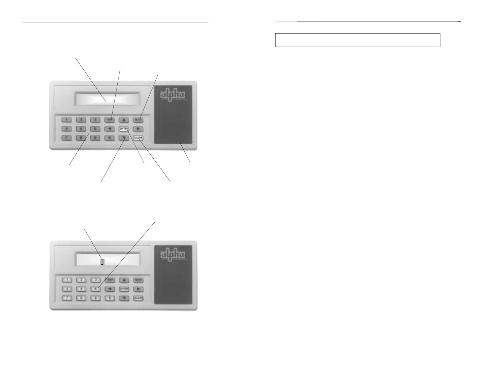
Intelligent Interface Device User Features
CLEAR
Key
MUTE
Key
TEST
Key
Illuminated LCD
Numeric
Keypad
Arrow
Keys
Alarms /
Status
Illuminated
(active) Keys
Input
Prompt
Modem Installation (optional)
The Intelligent Interface Device can be equipped with an optional modem
to provide long-range communications. Note: Installing the modem will
disable the RS-485 port.
To install the modem, you must first remove the CFR UPS's front panel
(page 9) to access the Intelligent Interface Device. Carefully plug the modem
module into the empty sockets as indicated (see component layout drawing
on page 11). Check that all of the legs on the module are properly seated into
the sockets. Note: It may be necessary to remove the RS-485 IC (label U3)
from the circuit board before installing the modem module. Upgrade EPROM
(U16) to a modem compatible version.
Once the modem module is installed, connect a standard modular
telephone cable, to the jack labeled "TELCO" to the telephone wall jack. A
second jack labeled "PHONE" allows reconnection of the telephone
equipment that may have been removed when the UPS was added. The
modem module installation is complete and ready for operation. To configure
the modem, see SET MODEM PORT (Section 3 "User Parameters").
Modem Operation
In order to use the modem, you must first enter the phone number and
alarm parameters you wish to monitor into the Intelligent Interface Device.
This is accomplished under the USER PARAMETERS screen. You will be
prompted to enter the phone number of the modem you want alerted and to
select the alarms that will initiate the call. Alarms that are not selected will be
disregarded (but still recorded in the EVENT HISTORY log). When a
selected alarm occurs, the Intelligent Interface Device will notify you, (via the
modem), at which time the alarms can be viewed on the terminal. To
determine the state of a call in progress, the following cryptic letters appear in
the upper-right corner of the Intelligent Interface Device's "Default" screen.
Diagnostic Codes for Pager and Modem
b
-
trigger(s) occurred (not detected or completed yet)
c
-
valid connection to modem (carrier detected)
d
-
off hook but no carrier detect (dialing)
1
-
waiting for "ID=" from pager BBS
2
-
waiting for "
3
-
waiting for message acknowledged
4
-
unknown response from paging system
after block sent. Set flags to repage.
5
-
got ACK. Wait till hang up. Good page.
6
-
got RS. Wait till hang up. Call again.
Note: Access to the MODEM setup is restricted and can only be accessed
by entering the security code (1111). Baud, parity, and triggers must be setup
using the front panel keypad. Alphanumeric setup must be done through a
remote terminal (RS-232 or modem). You may also dial into the Intelligent
Interface Device's modem to interrogate the unit.