Alpha Technologies CFR Intelligent Interface Device User Manual
Page 17
3. OPERATION
2. INSTALLATION
31
31
31
31
31
10
Press CLEAR to return to ALPHA TECHNOLOGIES default screen;
Press CLEAR to return to ALPHA TECHNOLOGIES default screen;
Press CLEAR to return to ALPHA TECHNOLOGIES default screen;
Press CLEAR to return to ALPHA TECHNOLOGIES default screen;
Press CLEAR to return to ALPHA TECHNOLOGIES default screen;
Press CLEAR again to return to the OPENING MENU.
Press CLEAR again to return to the OPENING MENU.
Press CLEAR again to return to the OPENING MENU.
Press CLEAR again to return to the OPENING MENU.
Press CLEAR again to return to the OPENING MENU.
Maintenance Parameters,
continued
Max. PLL Slew Rate
Changing this value will alter the characteristics of how the Phase
Locked Loop responds when the CFR UPS resumes LINE PRESENT
operation after a line fault has been corrected.
Battery Warning Ref
Changing this value will alter the time before a LOW BATTERY WARNING
occurs. Decreasing this value will allow the batteries to drain more of their
charge before a warning is given. Increasing this value will allow more run
time between LOW BATTERY WARNING and SHUTDOWN.
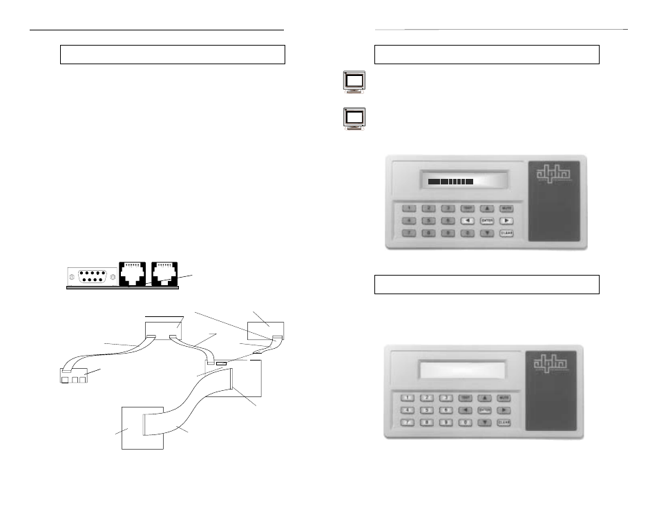
SERVICE PARAMETERS
SERVICE PARAMETERS
SERVICE PARAMETERS
SERVICE PARAMETERS
SERVICE PARAMETERS
Enter Security Code
UPS Front Panel Installation,
continued
7. Take the existing Standard Interface Device out of the front panel by
removing the board's four corner mounting screws. Unplug the LED
board's ribbon cable from the micro board and set the assembly aside.
8. Install the Intelligent Interface Device through the front panel and, using
the brass tab with the four screws (removed in step 7), secure the
assembly to the front panel. Connect the 10-conductor ribbon cable from
(J5) to the microcontroller's 10-pin header (see below).
9. Remove the cover plate from the upper-right side of the UPS's rear panel,
if applicable.
10. Install the Communications Board where the cover plate was located
using the two HEX-Standoff screws. The Comm. Board is installed from
the inside of the unit; the HEX screws are installed from the outside of the
rear panel.
11. Connect the 16-conductor ribbon cable to the Comm. Board's 16-pin
header (J10). Connect the other end of the cable to (J2) on the
Intelligent Interface Device board.
12. Reinstall the UPS top cover. Reconnect the 34-conductor ribbon cable to
the center of the microcontroller board (located on the CFR front panel).
Reinstall the front cover ensuring that the two locating pin guides seat
firmly into the holes in the top edge of the front chassis. After the pins are
firmly seated, swing the lower-edge of the front panel back into place and
tighten the two screws located in the lower grill.
13. Start the UPS and test it for proper operation (see Section 3).
79
78
Service Parameters
"SERVICE PARAMETERS" allows changes to the AC LINE detect
parameters. Since these parameters are pre-set at the factory and calculated
for optimum sensing, access to the various fields is restricted to factory
service technicians. Prior to accessing any section of this portion of the
program, contact Alpha Technologies for instructions and a password.
Maintenance Parameters Display. Note the number of digits selected
corresponds to the number to the right of the display.
Intelligent Interface Device Installation
Microprocessor
Board
Unplug ribbon
cable here to
facilitate
installation of IID
option
Power
Board
10-conductor
cable
34 conductor
cable
16-conductor
cable
J5
J2
J10
Comm. Board
Intelligent Interface Device
Remove cable and Standard Interface Board
20-conductor
cable
PHONE
TELCO
RS-232
COMMUNICATIONS
BOARD
(Installed in the CFR Rear Panel)
LINE PRESENT
LINE FAILURE
LOW BATTERY
WARNING
SHUTDOWN
SERVICE
FAST DETECT HIGH REF
FAST DETECT HIGH REF
FAST DETECT HIGH REF
FAST DETECT HIGH REF
FAST DETECT HIGH REF
- +11
LINE PRESENT
LINE FAILURE
LOW BATTERY
WARNING
SHUTDOWN
SERVICE