10 ecm alarm interface & communications, 9 ecm apu control interface, Top view plug-side view wire-insertion-side view – Alpha Technologies AlphaGen PN-6x-T 7.5kW 48VDC - Installation and Operation Manual User Manual
Page 78
78
745-020-B0-003, Rev. C
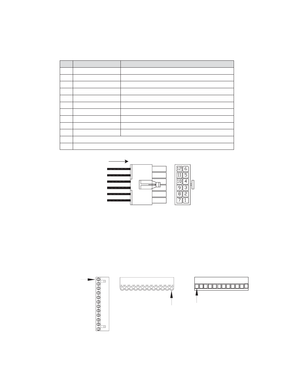
Fig. 8-9, APU Control Interface
8.10 ECM Alarm Interface & Communications
Terminal 1
Top View
Plug-side View
Wire-insertion-side View
Terminal 1
Terminal 1
Fig. 8-10, ECM, SCM Connector Arrangement
Pin
Description
Function
1
+12V Ignition Battery
Ignition Battery Fused 12V from APU
2
Neg. Ignition Battery
Ignition Battery Negative from APU
3
Low Oil Pressure
Active LOW signal denotes low oil pressure.
4
Over-temp
Active LOW signal indicates Over-temp.
5
Start Command
Active LOW from ECM activates APU Start relay.
6
Common (Start – Stop)
Common return between START and STOP relays.
7
Stop Command
Active LOW from ECM activates APU Stop relay.
8
Over-speed
Active LOW signal denotes engine RPM was exceeded.
9
Over-crank
Active LOW signal denotes Over-crank Limit is reached.
10
Engine Run
Active LOW signal denotes the engine is running.
11
Not Used
12
Not Used
8.0 Interconnection,
continued
8.9 ECM APU Control Interface
The interface control is a 12-pin (2x6 row) Mini Mate-’N’-Lok style connector.
J4
RE A R
V I E W
WI RE
SI DE
RE A R
V I E W