6 ecm alarm overview, Red yellow green – Alpha Technologies AlphaGen PN-6x-T 7.5kW 48VDC - Installation and Operation Manual User Manual
Page 45
745-020-B0-003, Rev. C
45
4.0
The Engine Control Module, continued
4.6 ECM
Alarm
Overview
Alarms are indicated in three ways: ECM LEDs, RS-485 communications, and alarm
contact closures on the ECM transponder interface. Alarm indications on the ECM LEDs are
displayed by pressing the service reset button momentarily. Pressing the service reset switch
again will reveal the next alarm in the list. When the alarm list has been exhausted, all LEDs
will fl ash several times and then return to their normal functions. Placing the RAS switch to
the STOP position for three (3) seconds, then switching back to AUTO will clear any
latched alarms and start the generator if the cause of the alarm has been corrected.
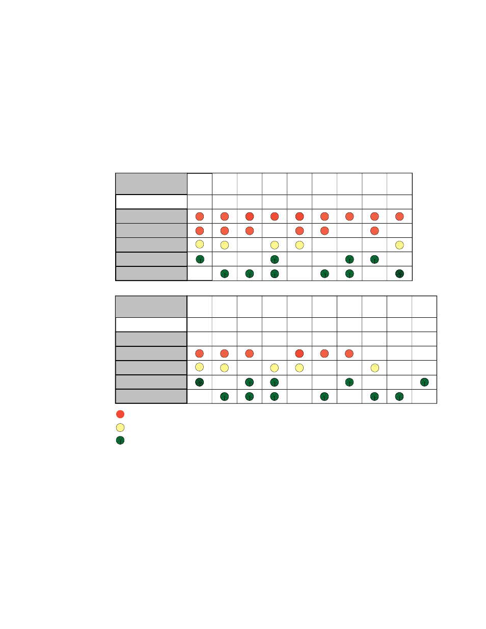
The following table shows the LED patterns and the alarms they represent.
1. (LO)* Low Oil Pressure
2. (OT) Engine Over-temp
3.
(OS)* Engine Over-speed
4.
(OC)* Engine Over-crank
5.
(OV)* Alternator Over-voltage
6.
(GH)* Gas Hazard
7. (WI) Water Intrusion
8.
(PS)* Pad Shear
9. (LP)*** Low Fuel Pressure
10. (CF)*** Control Fail
11. (AO)
Alternator
OFF
12. (TF)* Self-Test Fail
13.
(IB) Low Ignition Battery
14. (AD)
Auto-mode
Disabled
15.
(TP) Tamper (Default, Disabled)
16.
(DC) DC Bus fault
17.
(ED) Engine Disable
18.
(LF)** Line Failure
19.
(SR)** Service Required
Legend: * = Latching Alarm
**
= Notifi cations
***
= Alarm “latches” after 5 activations
Table 4-2, Major/Minor Alarm Indications and Notifi cations
(LEDs displayed on the ECM)
Major Alarms
Abbreviation
Major
Minor
Notify
Comm
System
1
2
3
4
5
6
7
8
9
LO
OT
OS
OC
GH
WI
PS
LP
OV
Major Alarms
Abbreviation
Major
Minor
Notify
Comm
System
10
11
12
13
14
15
16
17
18
CF
AO
TF
IB
TP
DC
ED
LF
AD
19
SR
Red
Yellow
Green