0 installation, continued, 6 ru battery storage* 5 ru equipment storage – Alpha Technologies FBE2322 Enclosure System User Manual
Page 27
27
031-314-B0-001, Rev. A (12/2012)
2.0 Installation, continued
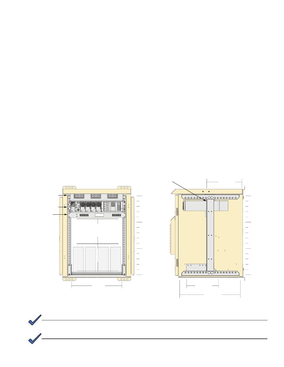
2.8 Equipment Installation, FBE2322-ENC
The FBE2322 Enclosure system's modular design and flexibility allow for a wide variety equipment
installation options. A standard configuration example is shown below. Consult an Alpha Applications
Engineer for more details about approved configurations.
Standard Configuration Cordex with Battery Tray in Base Cabinet Example:
• AC Power Distribution Shelf
• Cordex™ CXRF-HP 48-1.2kW 19" Front Access Shelf System
- Configured for 120Vac input
- Provides 12.5A @ 48VDC, N+1
- Fully equipped shelf provides 2.4kW (12.5A max @ 48V)
- 2RU shelf
- Heat dissipation <154 BTU/hr, per rectifier module
• Telect Dual Feed 60A GMT fuse panel, 10A/10B position -48VDC
• 5 RU of additional Equipment storage
• 6 RU of battery storage with FBE2322-ENC standalone.
0 RU
5
10
15 RU
0 RU
5
10
15 RU
18.73"
Standard Configuration: Rack
mounted at holes 9 & 10 from
front of Enclosure
10.25"
16.5"
13.24"
1 2 3 4 5 6 7 8 9 10
A
15A GMT Fuse Max
Power
Alarm
15A GMT Fuse Max
1 2 3 4 5 6 7 8 9 10
( ) - 70HPL-FT Batteries shown; See
Table 1-2 on Page 10 for more battery
size information.
*
6 RU
Battery Storage*
5 RU
Equipment Storage
Cordex Shelf
System (2RU)
AC Power
Distribution (1RU)
GMT Fuse
Panel (1RU)
Fig. 2-14, FBE2322-ENC Standard Equipment Configuration Example
Rack height is shown in Rack Units (RU); 1 RU = 1.75".
NOTE:
For wiring diagrams and alarm information, see Alpha p/n 031-314-08 Wire Diagram FBE2322 System.
Consult an Alpha Applications Engineer for further information about enclosure configurations.
NOTE: