0 installation, continued – Alpha Technologies FBE2322 Enclosure System User Manual
Page 18
18
031-314-B0-001, Rev. A (12/2012)
2.0 Installation, continued
2.4
Enclosure Installation, H-Frame Mounting continued
Most codes require the base of the enclosure to be located a minimum height from the ground. Always
verify mounting height requirements before proceeding.
Recommended Customer Supplied Tools and Materials:
• Ratchet with 5/8” (19mm) socket
• Level
• Four 7/16-14 x 1" (M12 x 25mm) hex head stainless steel bolts
• Eight 7/16" stainless steel flat washers
• Four 7/16"-14 (M12) lock washers
• Four 7/16"-14 (M12) hex nuts
• Structural slotted channel with mounting hardware
Procedure:
1. The FBE2322 Enclosures may ship with mounting brackets turned inward for convenience during
shipping. Remove the bracket mounting hardware and remount the brackets turned outward (see
Section 1.4).
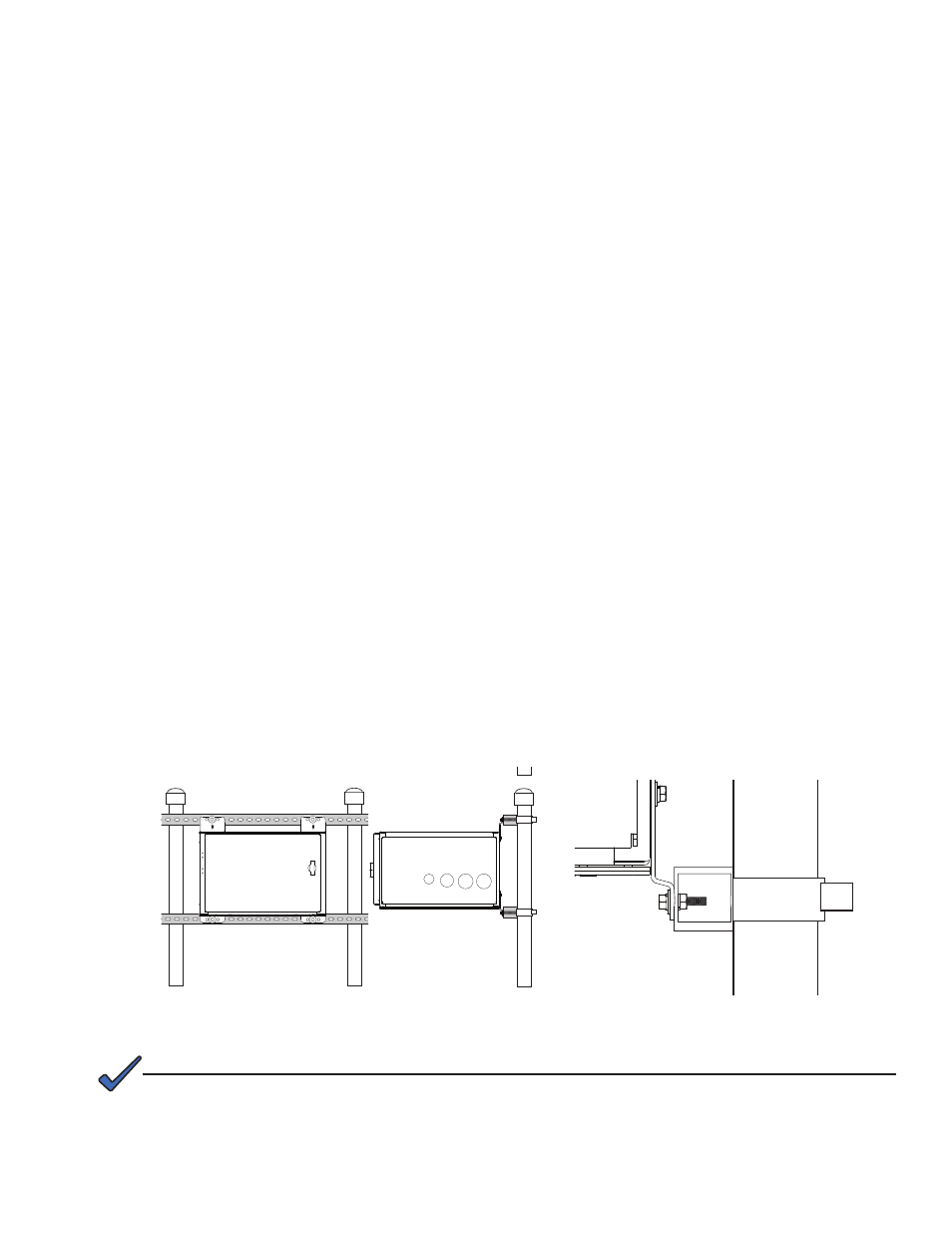
2. Position the enclosure on an H-frame of structural slotted channels 17" apart (for FBE2322-AEE) on
center (see Fig. 2-4).
3. Loosely attach the enclosure to the structural slotted channel using (4) 7/16"-14 x 1" (M12 x 25) hex
head stainless steel bolts, (8) 7/16" (M12) lock washers, (4) 7/16" stainless steel flat washers, and (4)
7/16"-14 (M12) hex nuts (see Fig. 2-5).
4. Using a level, ensure that the enclosure is parallel to the ground, and final tighten all mounting
hardware.
5. The enclosure is now ready for grounding (see Page 26) and equipment installation.
Fig. 2-4, FBE2322-AEE H-Frame Mounting Example.
Fig. 2-5, FBE2322-AEE H-Frame Mounting
Hardware Detail.
The optional lifting ears may be used to raise and position the empty enclosure. Lifting ears may ship
reversed.
NOTE: