Cla-Val 750-60 User Manual
Page 6
The Model 100-42 valve in 6" through
12" sizes are constructed with separa-
ble "slip-on" style flanges. Furnished
standard in either class 150 or 300
raised face type, the flanges are
removable and interchangeable. The
class 150 flange may be bolted up to
class 125 pipeline flanges and the
class 300 flange may be mated
against a class 250 flange.
Locate pilot system port connections
at the top of valve in pipeline to allow
easy air venting. A line size strainer is
recommended, mounted on the valve
inlet.
The valve should be given a visual inspec-
tion before installation to be sure no foreign
materials have collected inside the valve
during shipment or storage.
Pipelines should be flushed out before the
valve is installed in the system. New sys-
tems, especially, should be cleaned as con-
taminates such as welding beads, scale,
rocks, etc. are commonly contained within
the pipeline.
The valve should be installed in a location
allowing sufficient working space around
the valve to provide easy access for main-
tenance and removal for servicing.
For 2", 3", and 4" sizes only. Insert the lower
half pattern of stud bolts through the bolt
holes of the upstream and downstream
pipeline flanges.
For 2" & 3" valves only. The 125 and 150
series flanges use a different number of
bolts than the 250 and 300 series flanges.
Hence, the wafer valve body configuration
is inherently self centering regardless of the
flange used.
Install the valve between the flanges being
sure to include the appropriate flange gas-
kets between each end of the valve and the
mating pipe flange.
Note: The valve must be installed with the
flow arrow on side of body pointing to the
downstream piping section. Cla-Val 700
Series valves may be installed in any posi-
tion in either vertical or horizontal installa-
tions without any effect on valve operation.
Insert the remaining stud bolts and nuts and
tighten evenly using a diagonal cross-over
type pattern.
For the 4'' valve, ANSI pipe flanges use an
8 bolt pattern regardless of pressure rat-
ings, although the 250 and 300 series use
larger bolts on a larger bolt circle. The 4"
valve can be centered in the larger 250 and
300 class flanges by rotating the valve body
into full radial contact with the bolt studs
prior to tightening.
INSTALLATION
PROCEDURE
2.
3.
4.
4a.
6.
7.
1.
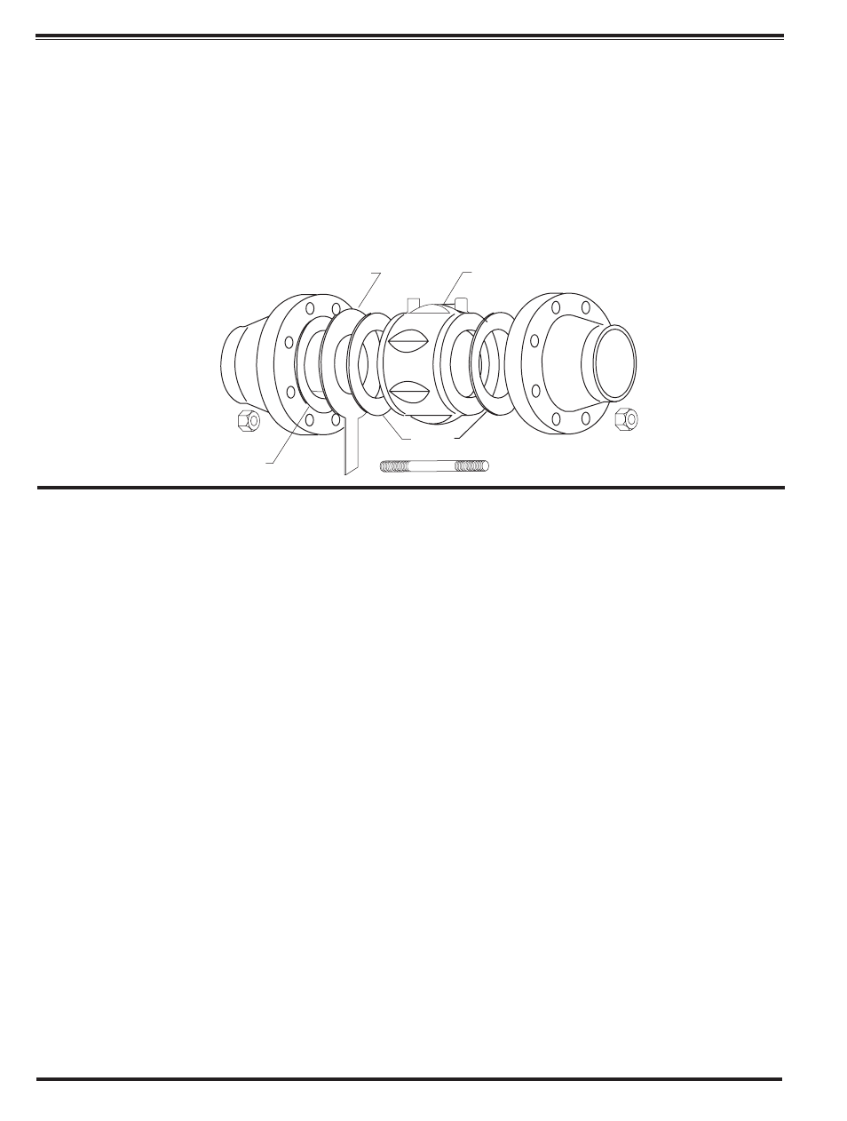
Gasket
Gasket
Recommended Strainer
Model 100-42 Roll Seal Valve
The Cla-Val Model 100-42 Roll Seal
valve in 2", 3", and 4" sizes are
designed to mount between standard
pipe flanges (ANSI 125, 150, 250, and
300 series) as a wafer type valve. The
outer portion of the valve body is con-
structed with fluted (recessed) sec-
tions to provide clearance for the class
125 and 150 flange bolt pattern while
the basic outside diameter of the body
centers within the class 250 and 300
flange bolt pattern.
If an inline basket type strainer is to be
included in the installation, insert the strain-
er into the upstream pipe, making sure a
gasket is placed between the strainer and
the upstream flange.
4b.
5.