Cla - val – Cla-Val 750-60 User Manual
Page 16
Install the range spring (Item 19) onto the
upper diaphragm plate and install the
spring pad (Item 16) onto the spring.
Set the spring housing (Item 20) onto the
diaphragm and install the eight body
screws (Item 10). Tighten the body screws
uniformly using a diagonal pattern to pre-
vent uneven loading on the diaphragm.
Install the adjustment screw assembly
(Item 14), including lock nut (Item15) and
adjustment cap (Item 11) on the spring
housing.
Remove the adjustment cap (Item 11).
Loosen the adjustment screw lock nut
(Item 15).
Turn the adjustment screw (Item 14) to
obtain the desired controlled pressure set-
ting. To increase the pressure setting, turn
the adjustment screw clockwise. To
decrease the pressure setting, turn the
adjustment screw counterclockwise.
Tighten the adjustment screw lock nut and
replace the adjustment cap.
Thoroughly clean all parts prior to reassem-
bly. It is recommended that a light film of
grease or oil be applied to all "O" rings to
ease assembly into body. It is also recom-
mended that a heavy bodied grease be
applied to the ball tip of the adjustment
screw (Item 14) before assembly into the
spring housing.
Insert the seat and guide bushing, with "O"
rings in place, into the pilot body (Item 7).
Install the retaining ring (Item 8) into the
groove.
Place the upper diaphragm plate (Item 5),
the diaphragm (Item 3) and the lower
diaphragm plate (Item 6) onto the cap screw
(Item 9). Insert the cap screw into the
plunger (Item 2) and tighten. Be very careful
not to damage the plunger surface during
this operation. Wrench flats are provided on
the plunger to hold the part while tightening
the cap screw.
Slide the plunger into the guide bushing and
rotate the diaphragm to line up the clear-
ance holes in the diaphragm with the
tapped holes in the body.
Remove the adjustment cap (Item 11) and
the adjustment screw (Item 14) to fully
relieve compression of the range spring.
Remove the eight body screws (Item 10)
and lift off the spring housing (Item 20).
Remove the range spring (Item 19) and the
spring pad (Item 16).
Remove the diaphragm (Item 3) and
attached parts from the body.
Inspect the diaphragm for wear or damage
and inspect the plunger (Item 2) for signs of
erosion or damage, particularly in the area
of the seating surface.
If any part shows damage, take the assem-
bly apart and replace the damaged compo-
nent. Disassemble by removing the cap
screw (Item 9) from the plunger. Be very
careful not to damage the plunger surface
during this operation. Wrench flats are pro-
vided on the plunger to hold the part while
removing the cap screw.
Remove the retaining ring (Item 8).
Remove the guide bushing (Item 4) and the
seat (Item 1) from the body. An easy
method of removal is to insert the plunger
through the outer port of the body and push
against the back surface of the seat.
Inspect the ''O" rings (Item 12 and 13 and
the seat (Item 1) for damage. Pay particular
attention to the sealing edge on the seat
and replace any parts showing damage.
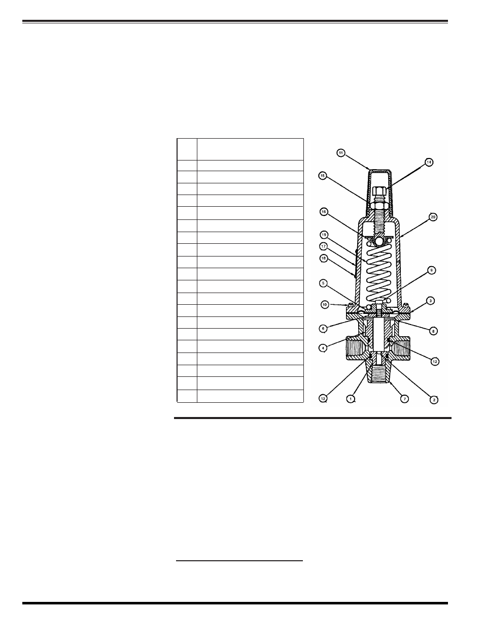
The procedure outlined below should be fol-
lowed when servicing the model RCBP
Back Pressure Control and Relief Pilot. Item
numbers, appearing with part names, are
keyed to the cross sectional parts list draw-
ing.
Disassembly
Pressure Adjustment
Reassembly
Item
No.
Description
1*
Seat
2
Plunger
3*
Diaphragm
4
Guide Bushing
5
Upper Diaphragm Plate
6
Lower Diaphragm Plate
7
Body
8
Retaining Ring
9
Cap Screw
10
Body Screw
11
Adjustment Cap
12*
"O" Ring
13*
"O" Ring
14
Adjustment Screw Assembly
15
Lock Nut
16
Spring Pad
17
Nameplate
18
Drive Screw
19
Range Spring
20
Spring Housing
* Recommended Spare Part
Specifications
When Ordering, Please Specify
1. Adjustment Range Desired
2. Materials Desired
Maintenance
Size
3/8" NPT Threaded
Adjustment Ranges
Temperature Range
Water: 180˚F Max.
psi: 10-90 (Silver)
Materials
25-150 (Red)
Body & Cover:
Cast Bronze ASTM B-62
50-300 (Blue)
Trim:
Brass & Stainless Steel 303
100-500 (Black)
Rubber:
Buna-N
®
(Fabric Reinforced)
Optional Materials
Bronze/Stainless Steel 316
Mounting Positions:
Stainless Steel 316
Multi-poise
Acetal Plastic
(operates in any position)
Viton & EPDM Rubber
.
Weight: 4 lbs
Pressure Rating
720 psi Max.
(All materials)
1.
2.
3.
4.
1.
2.
3.
4.
5.
6.
7.
8.
5.
6.
7.
1.
2.
3.
4.
CLA
-
VAL
© 2004
Cla-Val Printed in USA Specifications subject to change without notice.
P.O. Box 1325
•
Newport Beach, CA 92659-0325
•
Phone: 949-722-4800
•
Fax: 949-548-5441
•
E-mail: [email protected]
•
Website cla-val.com
N-RCBP (R-7/04)