Rcbp, Back pressure control and relief pilot, Model installation / operation / maintenance – Cla-Val 750-60 User Manual
Page 15
Plunger
Plunger
Restrictor
Restrictor
Diaphragm
Chamber
Loading
Pressure
Chamber
Loading
Pressure
Chamber
Loading
Pressure
Line
Supply &
Sense Line
OUTLET
OUTLET
INLET
INLET
MAIN VALVE
MAIN VALVE
Discharge
Line
Pressure Spring
RCBP
Back Pressure Control and Relief Pilot
The model RCBP pilot is used with Cla-
Val control valves to form a control unit to
function in either back pressure regulation
or pressure relief service.
Back Pressure Regulation Service
Accurately maintains upstream pressure
regardless of flow demand or downstream
pressure conditions.
Pressure Relief Service
Provides protection against excessive
main line system pressure.
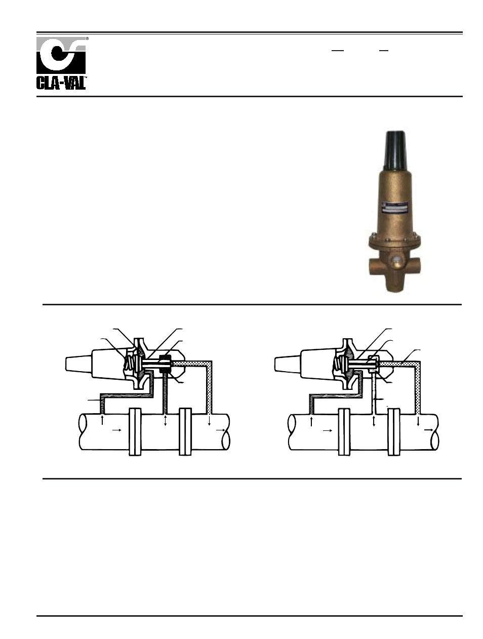
Figures A and B schematically depict the
RCBP connected to a hydraulically oper-
ated valve.
Upstream pressure is supplied to the
diaphragm chamber. From here it is trans-
mitted to the loading pressure chamber
through the restrictor (formed by an axial
groove along the plunger guide bore).
When the upstream pressure is less than
Installation
The model RCBP pilot has one inlet port
(marked "sense"), two loading ports
(marked "loading") and one outlet port. A
flow arrow is stamped on the side of the
pilot body, near the outlet port, indicating
flow direction through the pilot. The sec-
ond loading port is an auxiliary port and
may be used for mounting of a pressure
gauge.
The pilot may be mounted in any desired
position. When installing the model
RCBP as a pilot control on a main valve,
connect the pilot as follows:
Connect one of the "loading" pressure
taps on the model RCBP to the "loading"
pressure tap on the main valve body.
Plug the second "loading" pres-sure tap
on the pilot if it is not to be used.
Connect a line from the "sense" port of
the pilot to the "inlet" port tap on the
main valve body or to a pressure tap con-
nection in the upstream system as
desired.
Connect a line from the "outlet" port of
the pilot to the "outlet" port tap on the
main valve body.
All line connections should be a mini-
mum of 3/8" pipe or tubing size. If the
"sense" line connection is made to a
pressure tap location further than two
feet from the valve, the connecting line
should be stepped up at least one size.
It is recommended that a small strainer
be added in the sense line to the pilot to
prevent clogging.
the setting established by the pressure
spring, the plunger is in the closed position
as shown in Figure A, thus full upstream
pressure is provided to the control chamber
of the main valve. Since the control chamber
and upstream pressures are equal, the main
valve remains in the closed position. When a
rising upstream pressure exceeds the pres-
sure spring setting, the plunger is shifted off
the seat towards the open position shown in
Figure B. Flow is then established through
the pilot circuit and exhausted through the
discharge port into the downstream system.
As a result of pilot circuit flow, a pressure
drop is developed across the restrictor.
Hence, the pressure supplied to the control
chamber is reduced permitting the main
valve to open and maintain a steady
upstream pressure.
Principle of Operation
Figure A
Figure B
1.
2.
3.
4.
5.
MODEL
INSTALLATION / OPERATION / MAINTENANCE