Cdhs-18, 3/8" differential control, Cla-val – Cla-Val 49-01/649-01 Technical Manual User Manual
Page 22: Model installation / operation / maintenance
DESCRIPTION
The Cla-Val CDHS-18 Differential Control Valve is a normally open,
spring loaded, diaphragm type valve that operates hydraulically and is
designed to close on a rising differential pressure. When used as a pilot
control with Cla-Val Valves, it acts as a flow limiting control.
INSTALLATION
The Differential Control may be installed in any position. There is one
inlet port and two outlet ports in the body for either straight or angle
installation. The outlet port senses the high pressure or inlet to the differential
producing device. One of the outlet ports can be used for a gauge
connection. The port above the diaphragm (located in the control cover)
is used to sense the low pressure or outlet side of the differential producing
device. A flow arrow is marked on the body casting.
OPERATION
The Differential Control is normally held open by the compression spring
and the sensing pressure above the diaphragm. When the rate of flow
through the main valve increases, the sensing pressure above the
diaphragm of the control decreases and the higher pressure at the outlet
port closes the control; which, in turn, closes the main valve. When the
rate of flow through the main valve decreases, the sensing pressure
above the diaphragm increases. This opens the control and in turn
opens the main valve. This action causes the main valve to modulate,
limiting the flow rate to the setting of the control.
ADJUSTMENT
The Differential Control Valve can be adjusted to limit the rate of flow as
specified on the data plate. Rate of flow adjustment is made by turning
the adjustment screw to vary the spring pressure on the diaphragm. The
greater the compression on the spring the higher the flow rate.
1. Turn the adjustment screw in (clockwise) to increase flow rate.
2. Turn the adjustment screw out (counterclockwise) to decrease flow
rate.
DISASSEMBLY
The Differential Control Valve should be removed from the Hytrol Valve
assembly. Make sure that pressure shutdown is accomplished prior to
disconnecting assembly. During disassembly inspect all threads for dam-
age or evidence of cross-threading.
NOTE: A bench vice equipped with soft brass jaws should be used to
hold the valve body during disassembly and reassembly. DO NOT tighten
vice jaws more than enough to hold unit firmly. Excessive pressure may
spring or crack casting
1. Remove adjusting screw cap (16).
2. Loosen lock nut on adjusting stem assembly (9) and turn
adjusting screw counterclockwise to relieve tension on spring.
3. Remove bottom plug (8) and gasket (6).
4. Remove disc retainer assembly (5) and inspect sealing surface for
damage or wear. Replace if necessary.
5 Remove 8 screws (12) and carefully Iift off cover (2) spring guide
(10)
and spring (13) can now be removed.
6. Remove diaphragm assembly.
7. Remove diaphragm nut (7) and diaphragm washer (4).
8. Remove diaphragm (3), inspect for damage and replace if neces-
sary.
9. Inspect all parts for damage, corrosion, wear, foreign particles, and
cleanliness.
10. Repair minor nicks and scratches, these may be polished out
using a fine grade of emery or crocus cloth.
REASSEMBLY
Prior to reassembly replace all parts which are damaged or worn. When
ordering replacement parts be sure to specify item, part number, and all
nameplate data.
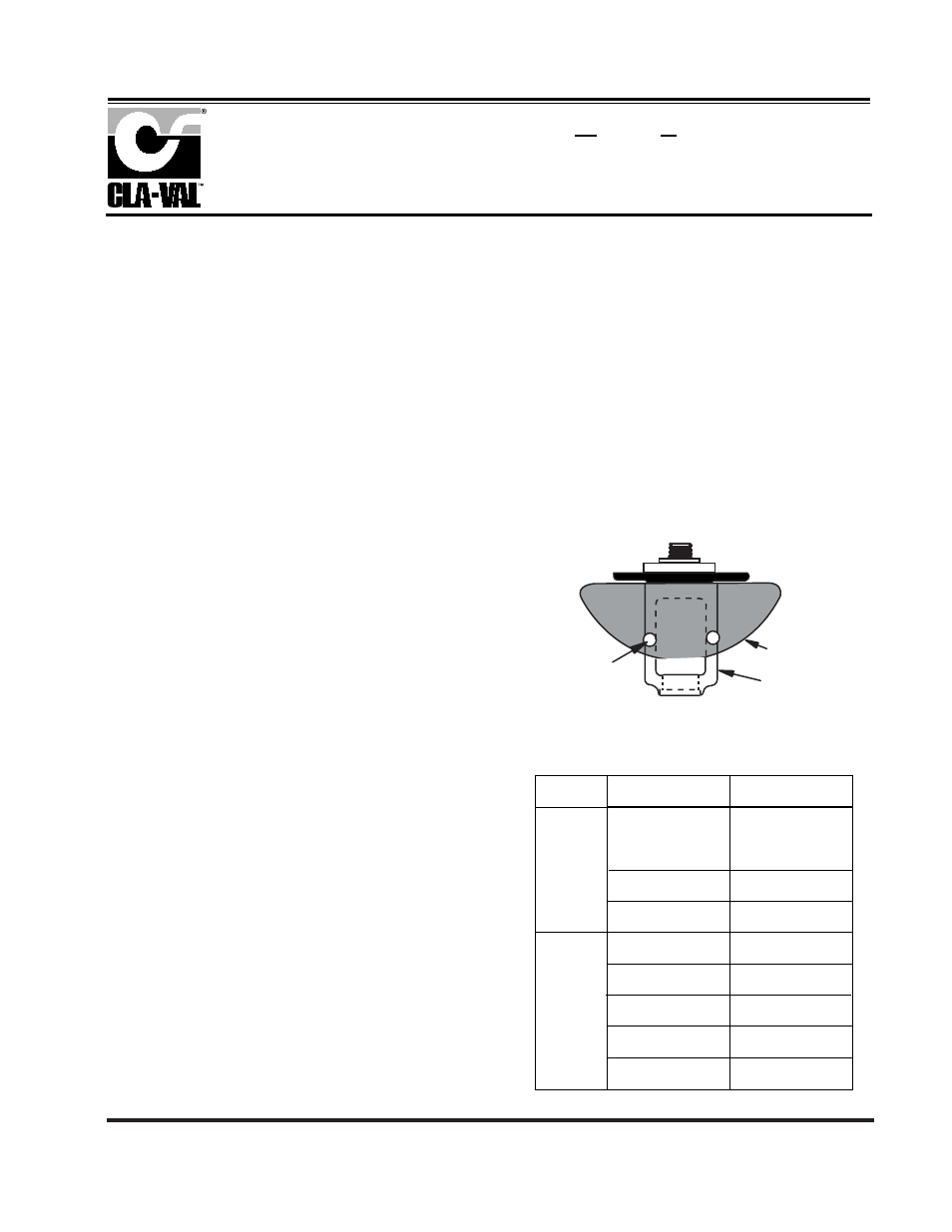
1. Place diaphragm (3) on top of yoke (11) place diaphragm
washer (4) over diaphragm with rounded edges down or next
to diaphragm. Screw on diaphragm nut (7) with the spring
guide shoulder in up position. The nut is not tightened at this time.
2. Align diaphragm flange holes with and folding diaphragm as
shown. Tighten diaphragm nut, retaining alignment shown.
3. Place yoke assembly in body (1) and screw the disc retainer
assembly (5) in until it bottoms.
4. Screw in plug (8).
NOTE: The yoke arms can be viewed through the 3/8" NPT
high pressure sensing outlet. There should be even spacing
between the yoke arms and the 3/8' NPT inlet boss seat
assembly. There must be no drag or friction between these
parts. If there is drag, repeat step 2.
5. Align diaphragm flange holes with the body holes and position
spring and spring guide (13) (10).
6. Replace cover (2) and secure with 8 screws (12).
7. Remove plug (8) and turn adjusting screw clockwise until the
disc retainer assembly moves down.
8. Replace gasket (6) and plug (8).
9. Replace cap (16).
3/8" Differential Control
CDHS-18
DIAPHRAGM
HOLES
DIAPHRAGM
YOKE
DIAPHRAGM HOLE ALIGNMENT
F
AILS TO
O
PEN
C
ONTROLLING DIFFERENTIAL
NOT CHANGING
C
HECK WITH GAUGE OR
MANOMETERS
D
IAPHRAGM ASSEMBLY STUCK
CLOSED
D
ISASSEMBLE AND FREE
F
OREIGN OBJECT UNDER
DISC RETAINER
D
ISASSEMBLE AND REMOVE
F
AILS TO
C
LOSE
I
NSUFFICIENT CONTROLLING
DIFFERENTIAL
I
NCREASE DIFFERENTIAL
F
OREIGN OBJECT UNDER
DISC
D
ISASSEMBLE AND REMOVE
D
ISPHRAGM ASSEMBLY STUCK
OPEN
D
ISASSEMBLE AND FREE
D
AMAGED DIAPHRAGM
D
ISASSEMBLE AND REPLACE
S
PRING COMPRESSED SOLID
B
ACK OFF ADJUSTING STEM
SYMPTOM
PROBABLE CAUSE
REMEDY
N
O SPRING COMPRESSION
S
CREW IN ADJUSTING STEM
SERVICE SUGGESTIONS
MODEL
INSTALLATION / OPERATION / MAINTENANCE
CLA-VAL
Copyright Cla-Val 2008 Printed in USA Specifications subject to change without notice.
P.O. Box 1325 • Newport Beach, CA 92659-0325 • Phone: 949-722-4800 • Fax: 949-548-5441 • E-mail: [email protected] • Website cla-val.com
©
N-CDHS-18 (R- 1/08)