Gotham 4 Elevations Wall Mount User Manual
Save these instructions, 4" elevations
INSTALLATION INSTRUCTIONS
4" Elevations
TM
Performance Downlight Pendant
Wall Mount
Upon receipt, thoroughly inspect for any freight
damage which should be brought to the
attention of the delivery carrier. Compare the
catalog description listed on the packing slip
with the label on the carton to ensure that you
have received the correct merchandise.
IMPORTANT SAFETY INFORMATION
For Your Protection, Read Carefully
WARNING - Risk of fire. Do not install
insulation within 3 inches of fixture sides
or wiring compartment, nor above the
fixture in such a manner as to entrap
heat.
1. Electric current can cause painful
shock or serious injury unless handled
properly. For your safety, always re-
member the following:
·
Turn off the power supply.
·
Ground the fixture to avoid poten-
tial electrical shocks.
·
Do not handle an energized fixture
or energize any fixture with wet
hands, when standing on a wet or
damp surface, or in water.
·
Double check all electrical connections
to be sure they are tight and correct.
2. Specific safety information concern-
ing lamps:
·
Match wattage of fixture and lamp
exactly.
·
Do not remove or insert lamp when
power is on.
·
Do not scratch glass or subject lamp
to undue pressure as either may
cause lamp breakage.
·
Protect operating lamp from sources
of moisture.
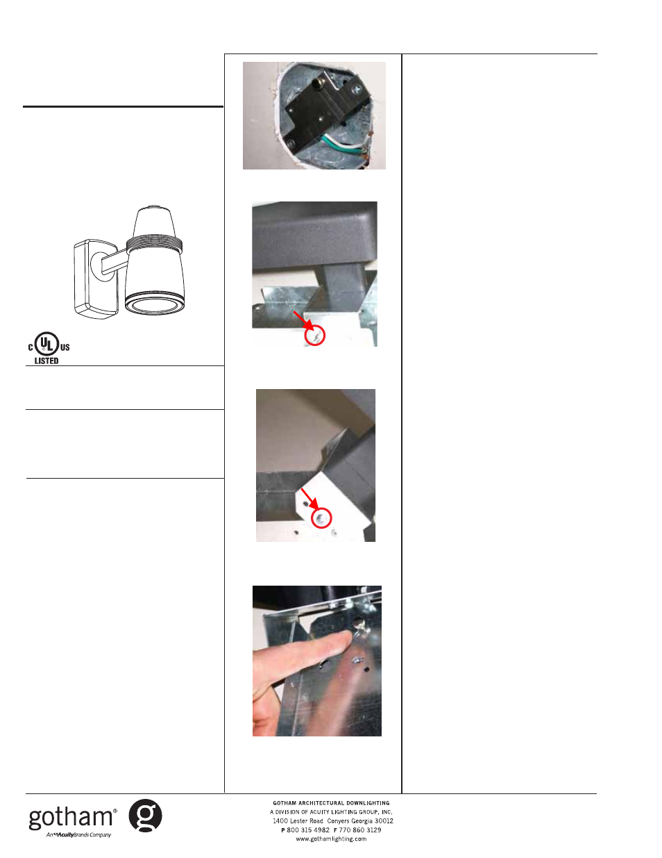
NEW INSTALLATION - J-box Preparation
1. Remove J-box mounting bracket from
hardware kit.
2 .Mount the bracket to the J-box
using the flush-head screws provided.
Be sure that the thumbscrew is on
top. FIGURE 1.
3 .Once bracket is installed onto J-box
securely, loosen thumbscrew 1/8
inch from bracket, but be sure not
to remove. BRACKET INSTALLATION
COMPLETE.
Fixture Preparation – Table Top
1 .Remove socket ASM from box, and
attach socket cup to reflector per
trim instruction sheet
2. After socket installation, make
connections between socket and
housing wires.
3. After both plugs are connected,
insert reflector/socket ASM into
fixture housing, pressing until clips
engage, and flange is flush.
4. Remove top and bottom screws
from wall canopy. Temporarily
store screws.
5. Slide canopy away to expose the
inner bracket assembly and side
screws. FIGURE 2.
6. Remove side screws from inner
bracket to allow the fixture arm to
pivot, then lock arm in open position
by temporarily inserting side-screws
into secondary locking holes on
each side. FIGURE 3.
Wall Mount of Fixture
1. Route supply wires from J-box
through the ½ inch hole of rear
bracket, being sure to pull them
through to allow wiring access.
Part No. CJ520700
©2006 Gotham
7/06
4" Elevations
TM
Page 1 of 2
Figure 4
SAVE THESE INSTRUCTIONS
Figure 1
Figure 2
Figure 3