Gotham DLWF 6 & 8 User Manual
Save these instructions, Directional lensed wallwash housing, Dlwf 6 & 8
IMPORTANT SAFETY INFORMATION
For Your Protection, Read Carefully
WARNING - Risk of fire. Do not install insu-
lation within 3 inches of fixture sides or wir-
ing compartment, nor above the fixture in
such a manner as to entrap heat.
1. Electric current can cause painful shock
or serious injury unless handled properly.
For your safety, always remember the
following:
• Turn off the power supply.
• Ground the fixture to avoid potential
electrical shocks.
• Do not handle an energized fixture or
energize any fixture with wet hands,
when standing on a wet or damp sur-
face, or in water.
• Double check all electrical connections
to be sure they are tight and correct.
2. Specific safety information concern-
ing lamps:
• Match wattage of fixture and lamp ex-
actly.
• Do not remove or insert lamp when power
is on.
• Do not scratch glass or subject lamp to
undue pressure as either may cause
lamp breakage.
• Protect operating lamp from sources
of moisture.
Upon receipt, thoroughly inspect for any
freight damage which should be brought to
the attention of the delivery carrier. Compare
the catalog description listed on the packing
slip with the label on the carton to ensure you
have received the correct merchandise.
INSTALLATION INSTRUCTIONS
Directional
Lensed Wallwash
Housing
DLWF 6 & 8
Part No. CJ52009
Page 1 of 2 - 5/06
WOOD OR STEEL JOIST CONSTRUCTION
On 24” centers (16” or 24” O.C. for 4” fixture)
utilizing solid type (non-accessible) ceiling
(drywall, plaster, etc.).
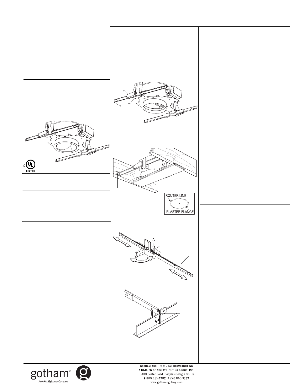
USING ROUTER FOR CEILING CUTOUT
1. Open lever (C) securing bar hangers -
bend ends of hangers 90° (D) to be used
as nailing tabs, center in the vertical slot,
and close lever (C) to lock; repeat on
opposite side.
Refer to Figure 1.
2. Secure a piece of plywood (E) to tempo-
rarily span the bottom of the joists to
support the fixture housing while
attaching the bar hangers (F) to the
joists. This will position the housing
correctly for drywall installer to provide
pilot hole (G) to locate fixture after ceiling
has been installed.
Refer to Figure 2.
3. PROCEED TO “FEED WIRE CONNECTION
TO FIXTURE J-BOX” ON NEXT PAGE.
Return and complete following steps
after feed wire connections have been
made.
4. Using 1/8” router follow outside of plaster
frame to cut hole in ceiling.
5. Loosen (2) 5/16” screws (A) 180° apart,
allowing fixture to drop down so bottom
edge of plaster flange will be slightly
above edge of ceiling material.
FOR CEILING THICKNESS OVER 3/4” REFER
TO FIGURE 5.
T-BAR CEILING INSTALLATION
1. Install ceiling panel in t-bar with ceiling
opening pre-cut. Ceiling opening must be
slightly larger than the outside diameter
of the plaster flange.
2. Open lever (A), expand bar hangers (B) to
approximately 24” and close lever to
lock. Refer to Figure 3.
3. Through an adjacent opening, position
the mounting frame with the plaster
flange passing through the pre-cut
opening with the notches on the bar
hangers engaging the t-bar.
4. Secure the bar hangers to the t-bar by
wire or wiretie (by others) or bending end
of bar hanger. Refer to Figure 4.
5. Open lever and adjust mounting frame
vertically so that the bottom edge of the
plaster flange is flush or slightly above
the bottom edge of the ceiling panel.
6. PROCEED TO “FEED WIRE CONNECTION
TO FIXTURE J-BOX” ON NEXT PAGE.
7.
If fine tune adjustment from below ceiling
is required: Loosen (2) 5/16” screws (A)
180° apart, allowing fixture to drop down
so bottom edge of plaster flange will be
slightly above edge of ceiling material.
PRIOR TO INSTALLATION
Read and familiarize yourself with the no-
menclature and instructions before starting
installation.
Turn off electricity at the breaker panel or
fuse box and follow National Electrical Code
regulations.
SAVE THESE INSTRUCTIONS
Figure 4
A
F
E
G
Figure 1
Figure 2
A
B
Figure 3