Vsw 2vga a • installation and operation, Figure 2-9 — removing the cover, Figure 2-10 — vsw 2vga a jumper locations – Extron Electronics VSW 2VGA A User Guide User Manual
Page 21
VSW 2VGA A • Installation and Operation
2-11
2
.
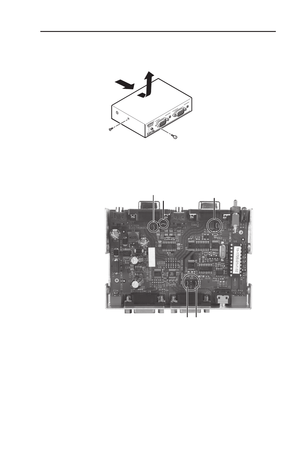
Remove the two screws on each side of the switcher
(figure 2-9). Remove the four connector nuts on the front
panel of the switcher. Lift the top cover off of the switcher.
VSW 2VGA A
INPUT 1
2
1
INPUT 2
Remove (4)
Connector Nuts
Remove (4)
Screws
Figure 2-9 — Removing the cover
JMP4
JMP3
JMP5 JMP6
FRONT PANEL
JMP1
EXTR
ON 20-881-
nn
x
ER:-
yyyyyyyy yyyy
Figure 2-10 — VSW 2VGA A jumper locations
3
.
Set the jumpers for the switcher. See figure 2-11.
4
.
Set the cover in place and resinstall the screws remove in
step 2.
There are five jumpers, numbered JMP1, and JMP3 thru JMP6,
that control daisy chaining on the VSW 2VGA A switcher (figure
2-10). Both data and power must be daisy chained from one
switcher to another.
- FOX Matrix 3200 (132 pages)
- ADA 2-4-6 Series (3 pages)
- ADA 6 Component (2 pages)
- AVT 100 (37 pages)
- AVT 200HD Setup Guide (4 pages)
- AVT 200HD User Guide (118 pages)
- AVTrac (482) User Guide (28 pages)
- CAT 5 Receivers (15 pages)
- CAT 5 Transmitters (15 pages)
- CD 400 (3 pages)
- CD 800 (15 pages)
- CD 900 (19 pages)
- CD 100 (18 pages)
- CSVEQ 100 D (2 pages)
- CSVEQ 100 D (38 pages)
- DA RGB_YUV Series (17 pages)
- CVEQ1, CVEQ1 WM, CVEQ1 AAP (17 pages)
- CVEQ_SVEQ 100 Series Setup Guide (2 pages)
- CVDA 6 EQ MX (3 pages)
- CVDA 6 EQ MX (2 pages)
- CVC 300 (8 pages)
- CVC 200 (4 pages)
- CVC 100 (2 pages)
- DDS 402 (54 pages)
- DDS 100 (54 pages)
- DA AV EQ Series (2 pages)
- DVC 501 SD User Guide (38 pages)
- DVC 501 SD Setup Guide (2 pages)
- DTP T USW 333 User Guide (26 pages)
- DTP T USW 333 Setup Guide (4 pages)
- DTP T USW 233 User Guide (26 pages)
- DTP T USW 233 Setup Guide (4 pages)
- DTP HDMI 330 User Guide (19 pages)
- DTP HDMI 330 Setup Guide (2 pages)
- DTP HDMI 301 User Guide (23 pages)
- DTP HDMI 301 Setup Guide (2 pages)
- DTP HDMI 230 User Guide (19 pages)
- DTP HDMI 230 Setup Guide (2 pages)
- DTP HDMI 230 D User Guide (22 pages)
- DTP DVI 330 User Guide (19 pages)
- DTP DVI 330 Setup Guide (2 pages)
- DTP DVI 301 User Guide (23 pages)
- DTP DVI 301 Setup Guide (2 pages)
- DTP DVI 230 User Guide (19 pages)
- DTP DVI 230 Setup Guide (2 pages)