Audio output, Wiring the remote/autoswitching connector, Wiring for rs-232 – Extron Electronics SW DVI A Series User Guide User Manual
Page 13: Enabling autoswitching, Audio output -12, Wiring the remote/autoswitching connector, Wiring for rs-232 -12 enabling autoswitching -13, Installation, cont’d
SW DVI A Series • Installation
Installation, cont’d
2-12
SW DVI A Series • Installation
2-13
1
.
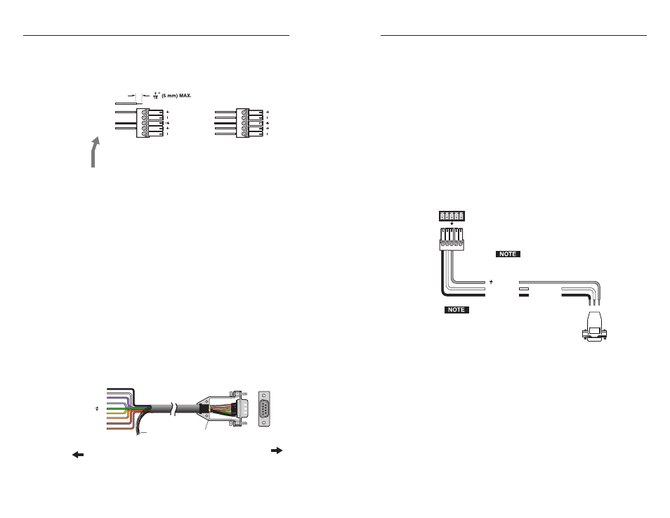
Wire the RS-232 cable to the five-pole captive screw plug,
provided with the SW2/SW4, as described below. Connect
only the red, orange, and green wires in the cable; and use
only the first three pins on the connector, starting at the
left.
a
. Connect the red wire to the first pin on the left, which
plugs into the Tx (transmit) port.
b
. Connect the orange wire to the second pin, which plugs
into the Rx (receive) port.
c
. Connect the green wire to the third pin, which plugs
into the ground port, marked with this symbol:
_
2
.
Plug the five-pole connector into the Remote/Auto-SW
receptacle on the switcher’s rear panel.
The following figure shows how to wire this shared connector
for RS-232.
If you use cable that has a
drain wire, tie the drain wire to
ground at both ends.
Connect a ground wire between
the switcher and the computer or
control system.
Remote/Auto-Sw
To Computer or
Control System
RS-232 Port
SW 2 or SW 4 DVI A Switcher
Rear Ranel
RS-232 Port
Tx Rx
A S
9 pin HD
Connector
Ground
Transmit
Rx
Receive
Tx
Green
Orange
Red
Transmit (Tx)
Receive (Rx)
3
2
RS-232/autoswitch connector pin assignments
Enabling autoswitching
You can set up the SW2/SW4 to automatically select the active,
connected input. If two or more inputs are active, the input with
the highest number is selected. When autoswitching is in effect,
the green Auto Switch LED on the front panel lights, and the
front panel input selection buttons are disabled.
Audio output
The 5-pole captive screw audio output connector is used for
both balanced and unbalanced audio. When the connector is
wired for unbalanced audio, the gain is unity.
For unbalanced audio, connect both sleeves
to the center contact ground. DO NOT connect
the sleeves to the negative (-) contacts.
C
Tip
Ring
Tip
Ring
L
R
Sleeves
Unbalanced Output
Tip
Sleeves
Tip
L
R
NO GROUND HERE
NO GROUND HERE
Balanced Output
Do not tin the wires!
Wiring the audio output connector
Wiring the Remote/Autoswitching Connector
The 5-pin, 3.5 mm Remote/Auto-Sw captive screw connector
is used for optional RS-232 communication and/or to enable
autoswitching between inputs connected to the SW2/SW4.
Wiring for RS-232
To connect your computer or control system to the RS-232
connector, use a male 9-pin, D-to-bare-wire RS-232 cable or a
universal control cable (UC 50', UC 100', or UC 200'). One end of
the UC cable is terminated with a female 9-pin D connector, and
the other end is unterminated. Wire the unterminated end to
the provided five-pin captive screw plug.
The following diagram shows the UC cable’s pin assignments.
1
5
9
6
7
6
5
4
3
2
1
8
9
Purple
Blue
Yellow
Orange (Rx)
Red (Tx)
Brown
Gray
Black
Connector Shell
Pin #
Color
UC Cable
Shield
Computer
or Control
System
SW DVI A Series
Switcher
Green ( )
UC cable pin assignment color codes