Power connector, Power connector -13, Preliminar y – Extron Electronics TP T Series Transmitters User Guide User Manual
Page 23
2-13
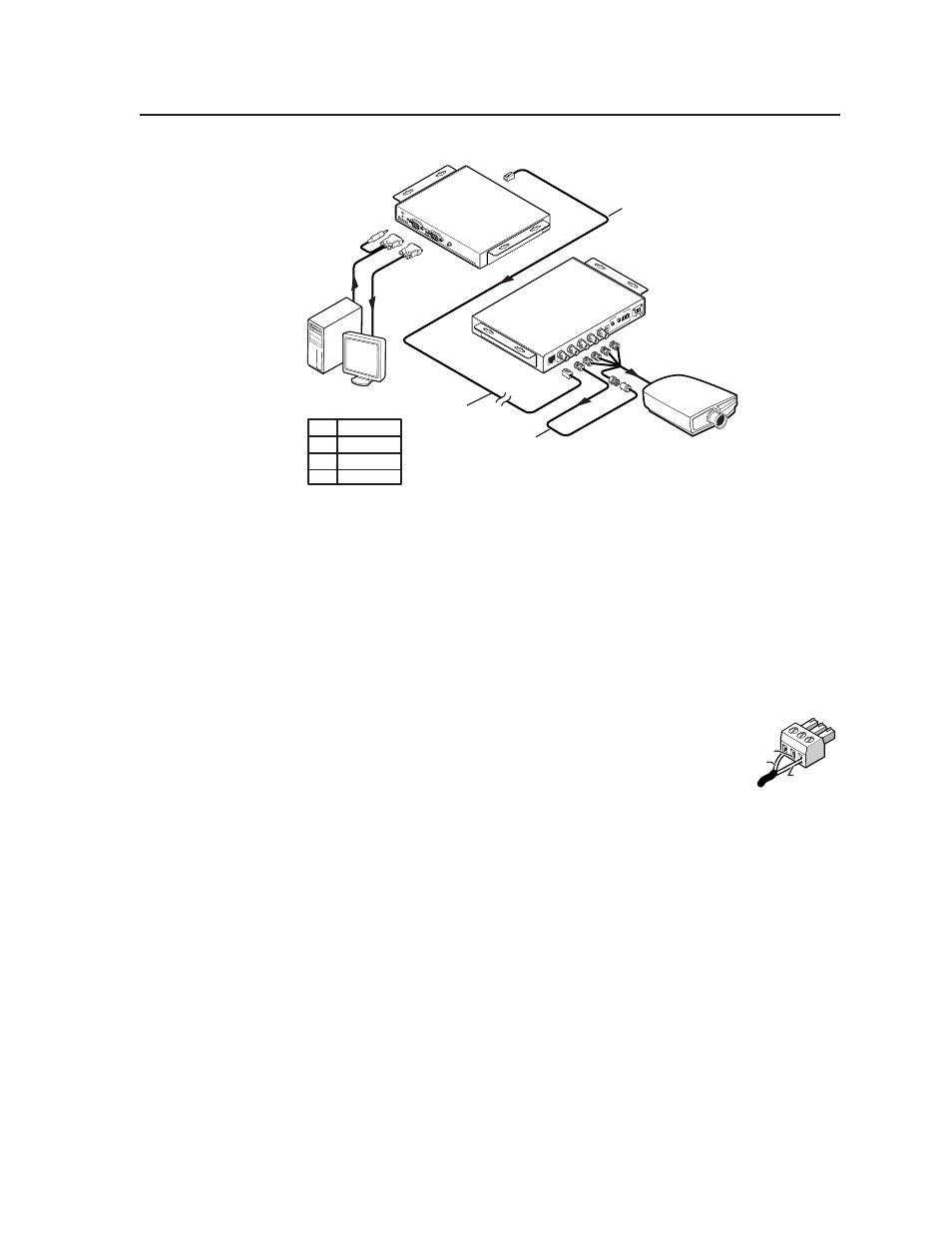
TP T Series Transmitters • Installation and Operation
PRELIMINAR
Y
TP T 15HD A
TP R BNC A
TP T
15H
D A
H-S
HIFT
BUF
FER
ED
COM
PUT
ER
INPU
T
AUD
IO
ID
P
IN
4
ID
P
IN
1
1
LOC
AL M
ONIT
OR
PC Computer
CAT 5 UTP Cable
Audio
LCD Projector
...
THEN insert a four foot
extension cable to equalize
TP skew for red video.
IF cable measurement
indicates that the pair
with wires
1 and 2 is
four feet shorter than
the other pairs...
RG
B IN
PU
T
RG
B O
UTPUT
R
G
B
H/HV
V
A
AU
DIO
L
R
B
SOG
C SYN
C
PO
WE
R
15V
.5A
DC
L
R
Pair RGB video
1, 2 Red
4, 5 Green
7, 8 Blue
Pair skew equalization example
Power connector
i
Power connector —
TP T BNC DA4
: Plug the external 15 V power supply into this captive screw
connector.
N
If the distance between the transmitter and receiver is too great for
the receiver to power the transmitter, the video image will be missing,
distorted, or noisy, or the receiver’s Manual/Auto LED flashes. The
transmitter requires a local 15 V power supply.
TP T 15HD A and TP T 15 HD AV
: If desired or for distances
over 300 feet (91 m), plug an external 15 VDC power supply
into this 3-pole captive screw connector. Wire the connector as
shown at right.
N
If you are using the TP T Series transmitter with a
TP R 15HD A receiver, you must use an external power supply to
power the transmitter. It cannot be powered via the TP R 15HD A
receiver.
Return
N/C
+15V