Extron Electronics RGB 118 Plus User Guide User Manual
Page 8
Extron • RGB 118 & RGB 118 PLUS • User’s Manual
Operation
Page 2-1
Operation of RGB 118 and RGB 118 PLUS
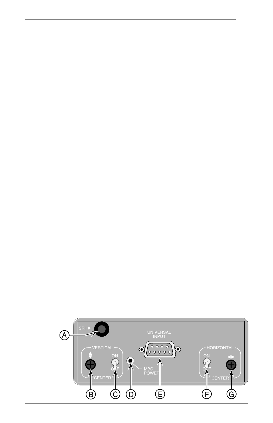
Front Panel
The following descriptions are keyed* to the RGB 118 PLUS
drawings below and on the facing page.
A
SRI Pushbutton Switch (RGB 118 PLUS ONLY)
Push and hold this button in to enable the RGB 118 PLUS SCAN-
RATE LCD to display the horizontal and/or the vertical scan rate
frequency of a monitor (See Using the SRI on Page 2-5 for details).
B
Vertical Center Control (RGB 118 PLUS ONLY)
Turning this RGB 118 PLUS control shifts the displayed image up
or down if the Vertical Center Switch is in the ON position.
C
Vertical Center Enable Switch (RGB 118 PLUS ONLY)
Enable/disable the RGB 118 PLUS Vertical Center Control – OFF
position disables and ON position enables.
D
MBC Power Connector
Provides 12 VDC for Extron MBC Buffers.
E
Universal 9 Pin Input Connector
The RGB 118 and RGB 118 PLUS video input is supplied through
this connector. Acceptable input types are TTL, Analog and ECL.
Connector pin assignments follow:
Pin #
ANALOG
DIGITAL (TTL or ECL)
1
Ground
Ground
2
No Connection
Red Prime
3
Red
Red
4
Green/Sync on Green
Green
5
Blue
Blue
6
No Connection
Green Prime
7
No Connection
Blue Prime
8
Horizontal/Composite Sync
Horizontal Sync
9
Vertical Sync
Vertical Sync
F
Horizontal Center Enable Switch
Enable/disable the Horizontal Center Control – Off position disables
and ON position enables.
G
Horizontal Center Control
Turning this control shifts the displayed image to the left or right.
* – Letters next to the descriptions are keyed to the circled letters in the
drawings on this and the next page.