Front panel controls and indicators, Installation and operation, cont’d, Tp receivers • installation and operation – Extron Electronics TP Receivers User Guide User Manual
Page 32: Figure 2-12 — tp r bnc a and tp r bnc av
TP Receivers • Installation and Operation
Installation and Operation, cont’d
2-20
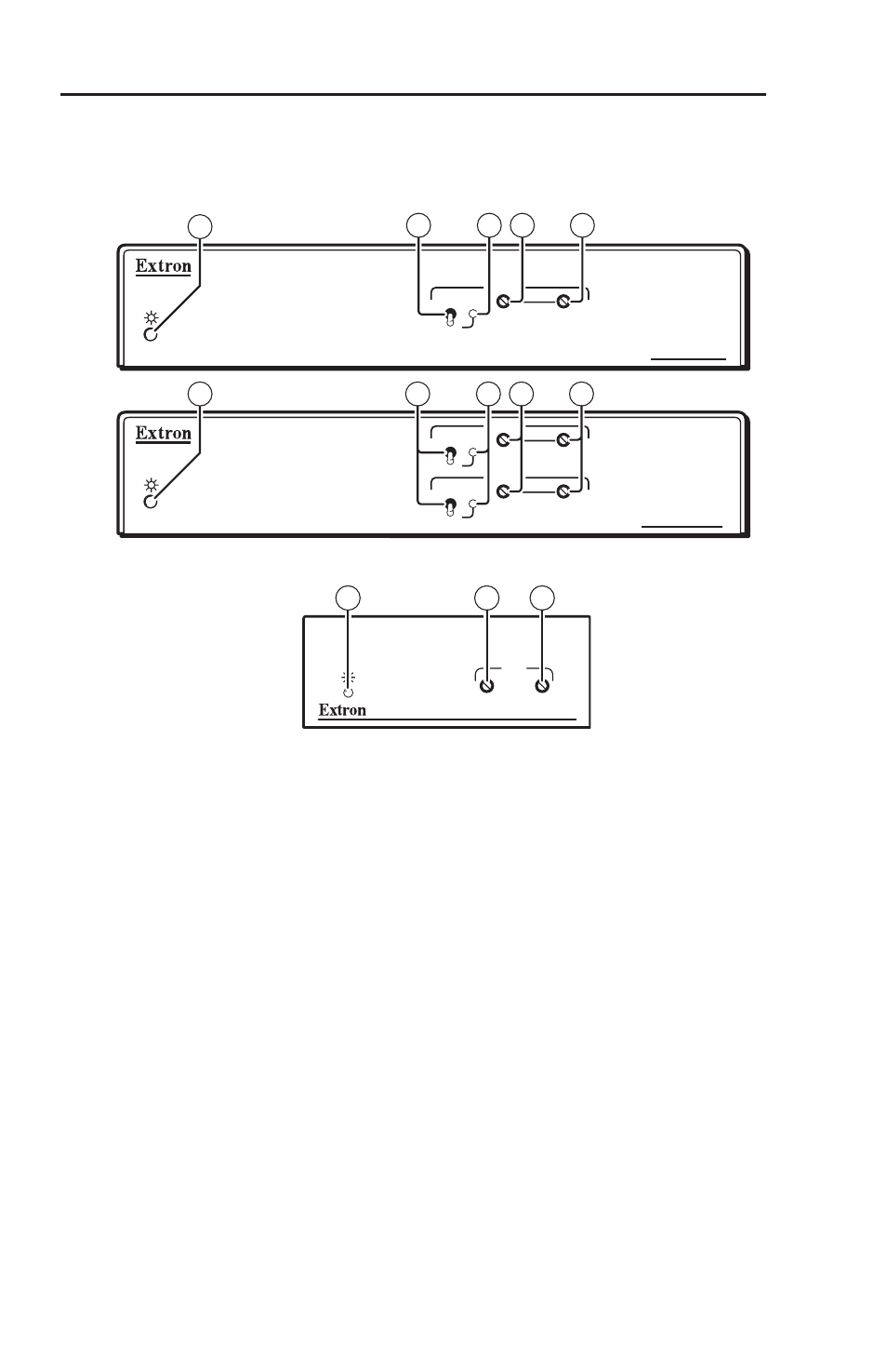
Front Panel Controls and Indicators
The TP R Receivers have similar controls and indicators as
shown below.
TP R BNC A
RGB
MANUAL
AUTO
LEVEL
PEAKING
1
3
4
5
2
TP R BNC AV
VIDEO
MANUAL
AUTO
LEVEL
PEAKING
RGB
MANUAL
AUTO
LEVEL
PEAKING
1
2
3
4
5
Figure 2-12 — TP R BNC A and TP R BNC AV
TP R 15HD A
RGB
PEAKING
LEVEL
1
4
5
Figure 2-13 — TP R 15HD A
a
Power LED
Amber —
indicates power is applied, but the receiver is not
connected to a transmitter.
N
On the TP R BNC AV if the composite video TP link is
used and the RGB link is not used, or if the transmitter
is a VTT001 this LED lights amber.
Green —
indicates a receiver is connected and any of the
following grounding conditions exist:
•
The receiver is powered by a local power supply
and the receiver output is connected to a device that
provides a reference ground.
•
The receiver is powered, is locally grounded, and the
receiver output is connected to a device that provides
a reference ground.
•
The receiver is receiving power from the transmitter,
a local monitor is connected to the transmitter, and
the receiver output is connected to a device that
provides a reference ground.