Termination of tp cable, Tp receivers • installation and operation, Figure 2-10 — tp cable termination – Extron Electronics TP Receivers User Guide User Manual
Page 29
TP Receivers • Installation and Operation
2-17
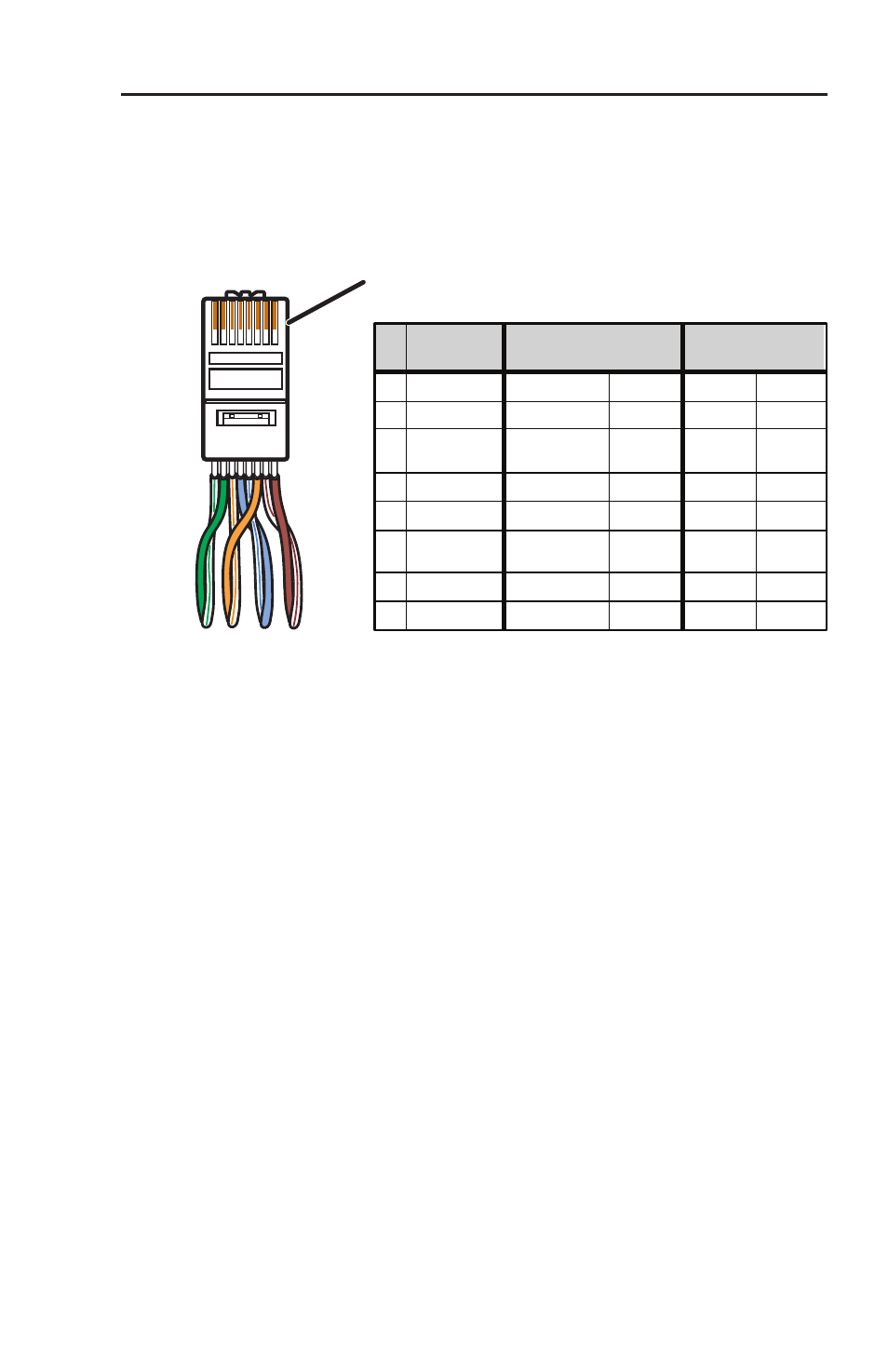
Termination of TP cable
Figure 2-10 details the termination of TP cables in accordance
with the TIA/EIA T 568 A wiring standards.
1&2
3&6 4&5
7&8
Twisted Pairs (4)
12345678
Pins:
* Audio can be jumpered to wire pair 7 and 8.
See Audio jumpers
in this chapter.
Pin
Wire color
RGB video and audio
AV Video and audio
Signal
Level
Signal
Level
1 White-green
Red/V. sync+
±0.35V
Video+
+0.35V
2 Green
Red/V. sync-
±0.35V
Video-
-0.35V
3 White-orange
Audio &
power
+15V with
±0.5 V
+15V
4 Blue
Green+
+0.35V
Reserved None
5 White-blue
Green-
-0.35V
Reserved None
6 Orange
Audio &
power
Audio+* &
power+
Audio-* &
power-
±0.5 V
0V
7 White-brown
Blue/H. sync+
±0.35V
Reserved None
8 Brown
Blue/H. sync-
±0.35V
Reserved None
RJ-45
connector
Figure 2-10 — TP cable termination
N
Enhanced Skew-free A/V cable is not recommended for
Ethernet/LAN applications.
This cable is specially designed for compatibility
with Extron Twisted Pair products, wired using the
TIA/EIA 568 A standard.
The green, brown, and blue pairs of this cable have
virtually identical lengths, and should be used to
transmit the RGB signals.
The orange pair of this cable has a different length and
should not be used to transmit RGB signals.