Installing the mlc 52 – Extron Electronics MLC 52 Series Quick Start Guide User Manual
Page 5
3
MLC 52 Series • Quick Start Guide
Installing the MLC 52
The MLC can be installed into a wall or furniture. Follow the instructions
appropriate to the mounting option you have selected.
Step 1
Prepare the installation site
as required for your MLC model (cut a hole in the wall
or furniture, and install an electric wall box and/or mounting bracket). See
“Mounting an electrical box” in chapter 2, “Installation,” of your MLC 52 User’s
Manual, for details on this procedure.
a
.
Refer to the appropriate template diagram in your user’s manual to find out
the dimensions of the opening required for the size of the wall box or
mounting bracket that you are using. If using both a wall box and mounting
bracket, use the dimensions on the bracket template.
b
.
Using a ruler, draw guidelines on the installation surface (wall or furniture)
where the opening for the bracket or wall box will be cut.
c
.
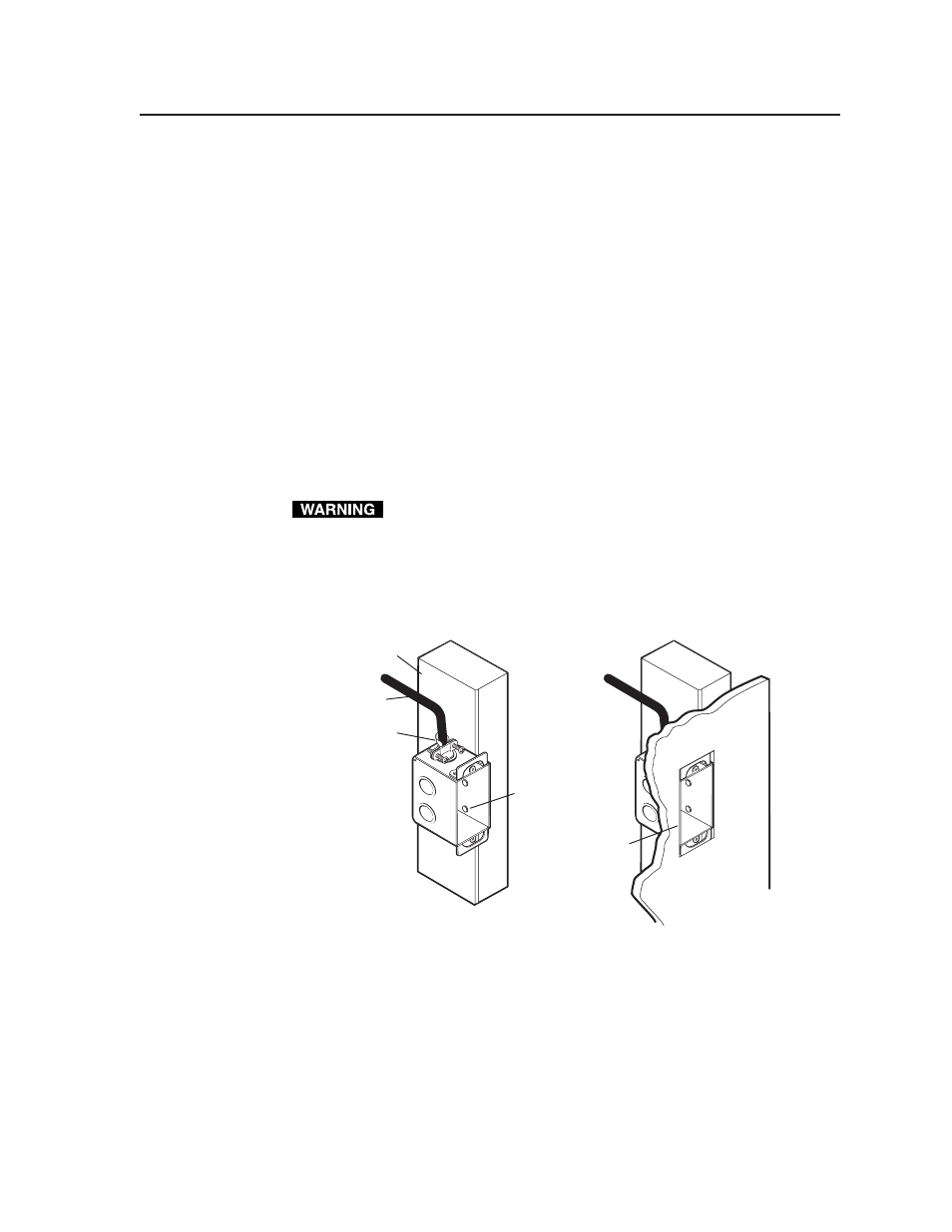
Feed cables through the wall box punch-out holes, and secure them with cable
clamps.
To prevent short circuits, the outer foil shield can be cut back to the point
where the cable exits the cable clamp. Both braided and foil shields should
be connected to an equipment ground at the other end of the cable.
d
.
Insert the wall box into the opening, and attach it to the wall stud or furniture
with nails or screws, leaving the front edge flush with the outer wall or
furniture surface. The illustration applies to all sizes of wall boxes.
Wall opening
flush with
edge of box
Installation
Cable
Cable Clamp
Screws or Nails
Wall Stud
Attaching a wall box to a wall stud
Step 2
Make and/or install button labels
as desired. By default, buttons are prelabeled
for your convenience. However, you can replace these labels with included button
labels. See “Replacing button labels” in chapter 2, “Installation,” of the user’s
manual for the procedure.