Mlc 52 series quick start guide, cont’d, Step 3, Step 4 – Extron Electronics MLC 52 Series Quick Start Guide User Manual
Page 12: Mlc 52 series • quick start guide 10
MLC 52 Series Quick Start Guide, cont’d
MLC 52 Series • Quick Start Guide
10
1
1
2
3
4
E
ON
2 3 4
Tx
IR OUT
GND
IR IN
GND
+ 12V
1
1
2
3
4
E
ON
2 3 4
Tx
IR OUT
GND
IR IN
GND
+ 12V
Less Than 6”
IR Beaming
Transmitting MLC
Receiving MLC
1
ON
2 3 4
1
ON
2 3 4
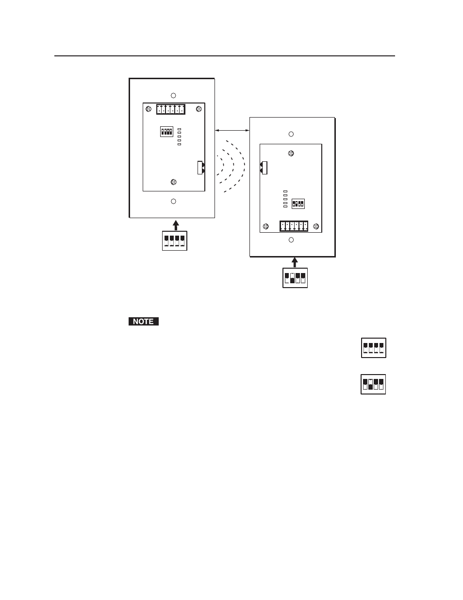
Setting up donor and receiver units for wireless data transfer
The illustrations show the standard (1-gang sized) MLC 52. However, the
procedures are the same for the VC models.
Step 3
Leave all configuration switches set to Off
on the MLC that will
be transmitting the data.
Step 4
Set switch #2 to On and all other switches to Off
on the MLC that
will be receiving the data.
When the two units are placed in the proper position for data transmission, and the
receiving unit’s configuration switch #2 is set to On, the transmitting and receiving
units detect each other’s presence, and the data transfer begins automatically.
During data transfer, the front panel buttons act as progress indicators. The
buttons on both the transmitting and the receiving MLCs blink sequentially in
clockwise order, starting with the ON button in the upper-left corner (see the
diagram on the next page). This cycle repeats until transfer is complete.
Receiving MLC
1
ON
2 3 4
Transmitting MLC
1
ON
2 3 4