F g j k – Extron Electronics MTP_HDMI U R User Guide User Manual
Page 12
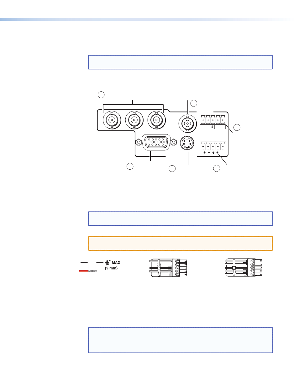
f g j k
Analog signal outputs — Connect suitable devices for analog signals:
RGBHV, RGBS, component (Y, R-Y, B-Y), S-video (Y/C), and composite video.
NOTE: The video signals detected on the MTP input are directed to the appropriate
analog outputs.
Connect as shown below:
RGB
VID
Y/C
B-Y
Y
R-Y
ANALOG OUTPUTS
RS-232
Tx Rx
SPARE
1
MONO AUDIO
2
Connect for
RGBHV and
RGBS Output
Connect for
S-video Output
Connect These 3 BNCs for
Component Video Output
Connect for
Mono Audio
Output
Connect for
RS-232 Control
(Analog Side)
Connect for
Composite Video Output
11
10
9
8
7
6
Figure 6.
Analog Output Connections
h
Audio output — Connect a suitable audio device to this 5-pole captive screw
connector for a balanced or unbalanced, dual mono audio signal.
NOTE: The audio signal is detected on the analog MTP twisted pair input and then
distributed to the audio output connector.
Wire the connector as shown below:
CAUTION: For unbalanced output, connect both sleeves to the center (ground)
terminal. DO NOT connect the sleeves to the negative terminal.
L
MONO A
UDIO
R
L
MONO A
UDIO
R
Unbalanced Output
Balanced Output
Do not tin the wires!
Mono output 1-
Sleeve(s)
Mono output 1+
Mono output 2+
Mono output 2-
Sleeve(s)
Mono output 1
Mono output 2
NO GROUND.
NO GROUND.
Figure 7.
Audio Connector Wiring
i
RS-232 port (analog side) — Connect a serial communications port to this 3.5 mm,
5-pole captive screw connector for bidirectional RS-232 control on the analog side.
See the "
Control Connector Wiring
" section, to wire the connector.
NOTE: The RS-232 port configuration by default is bidirectional RS-232 on the
digital input. The MTP/HDMI U R can be configured via the jumpers on the
main board. See the “
Setting the Jumpers
” section, for details.
The MTP/HDMI U R DOES NOT support IR control on the analog side.
MTP/HDMI U R • Cabling
6