Installation, Step 1, Step 2 – Extron Electronics MSG0808 User Manual
Page 3: Step 3, Step 4, Step 5, Step 6, Step 7
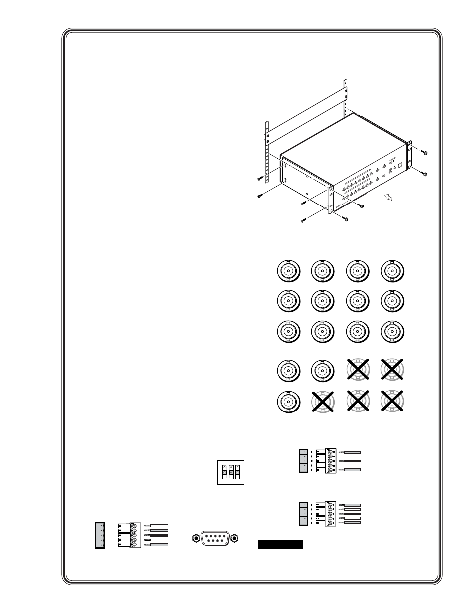
Quick Start — MSG0804 and MSG0808
Installation
Step 1
Turn off power to the switcher and all other
devices that will be connected.
Step 2
To rack mount the switcher, install the included
brackets, then mount the switcher. Otherwise,
install the four rubber feet (included) and place
the switcher on a desktop.
Step 3
Using video inputs 1 through 8, attach RGBHV,
RGBS, RGsB, RsGsBs, or component video to the
switcher using BNC connectors (see illustration
at right).
Step 4
Using audio inputs 1 through 8, attach audio
inputs to the switcher with 5-pole captive screw
connectors (see illustration below right).
Step 5
Connect up to four (MSG0804), or eight
(MSG0808), RGBHV, RGBS, RGsB, RsGsBs, or
component video output devices to the switcher
using the Video BNC connections (see illustration
below right).
Step 6
Connect up to four (MSG0804), or eight
(MSG0808) audio output devices to the switcher
using 5-pole captive screw connectors (see
illustration below right).
Step 7
If the switcher is to be connected to a computer
or host controller for remote control, connect the
host’s RS-232 cable to a 5-pole captive
screw connector and connect it to the
serial port on the switcher. Configure
the serial port for the type of control
you will be using (RS-232, RS-422, or
RS-485) by setting the dip switch
adjacent to the port. (See the serial port pinout
table on page 2-4).
Connecting the MSG0808
G
RGBHV
RGBS
Component,
RGsB,
RsGsBs
Component,
RGsB,
RsGsBs
B
H
V
R
V
G
B
HV
R
G
B
R
Y
B-Y
R-Y
V
H
V
H
Rack mounting the MSG0808
CAUTION
Connect the sleeve to ground
(Gnd). Connecting the sleeve to a
negative (-) terminal will damage
the audio output circuits.
RS-232
RS-422/RS-485
1 2 3
DB9 Pinout (Female)
5
1
9
6
Rx+
Rx-
Tx+
Tx-
Gnd
Rx+
Rx-
Tx+
Tx-
Gnd
RS-232/422-485
5-pole captive screw connector/socket
5
OUTPUT SELECT
6
7
8
MS
G
Serie
s M
atr
ix S
witch
er
1
2
3
4
1
2
3
4
5
INPUT SELECT
6
7
8
CANCEL
TAKE
BLANK
PRESET
VOLUME
MUTE
AUDIO
VIDEO
LEVEL SELECT
Unbalanced Input/Output
Tip
See Caution
Sleeve (s)
Tip
See Caution
Balanced Input/Output
Tip
Ring
Sleeve (s)
Ring
Tip
LR
OUT
LR
OUT