Cabling and features, Power, Control — serial (com) – Extron Electronics IPCP 505 Setup Guide User Manual
Page 2: Control — serial (com) 2, Ipcp 505 • setup guide (continued), Attention
2
IPCP 505 • Setup Guide (Continued)
Cabling and Features
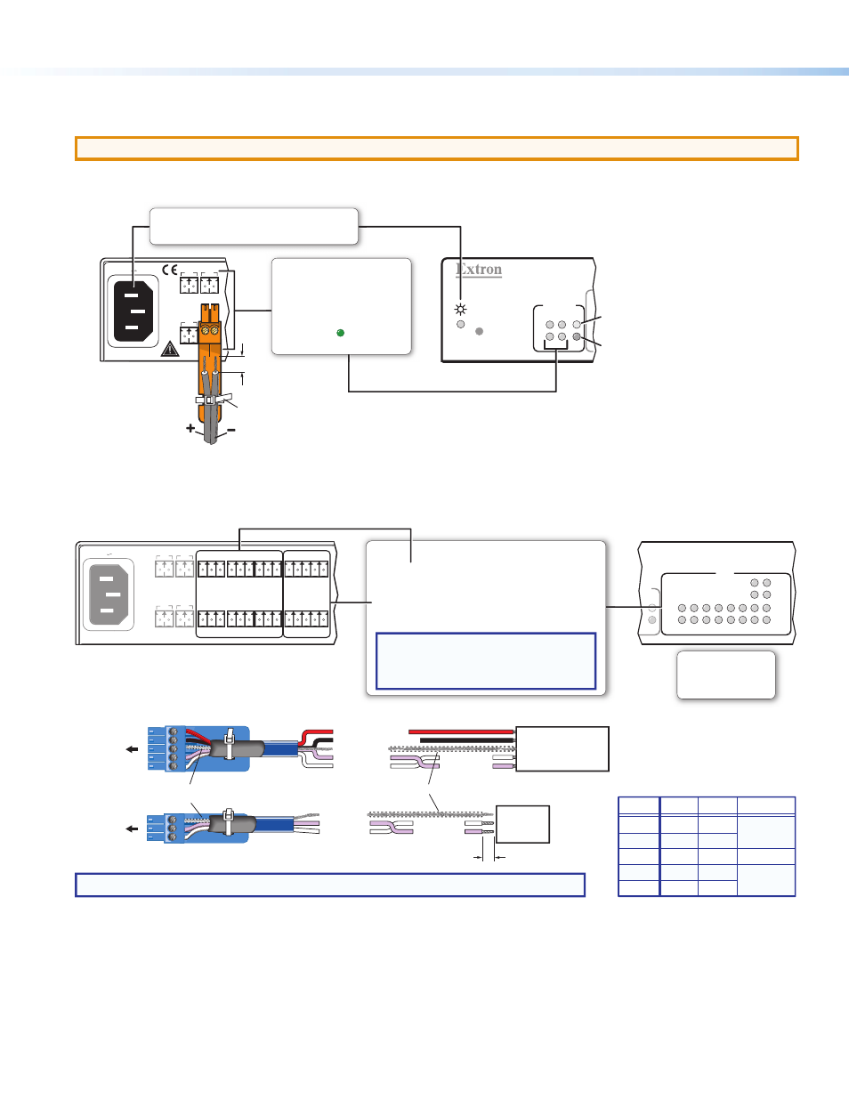
Attach cables using the following wiring diagrams as a guide. Full details are available in the IPCP 505 User Guide.
ATTENTION:
Installation and service must be performed by authorized personnel only.
Power
IPCP 505
T
T
T
R
SWITCHED
12VDC
3
1
4
OVER
2 LIMIT
R
R
R
5A MAX
100-240V 50-60Hz
SWITCHED 12VDC
40W MAX TOTAL
+ - + -
+ - + -
1
2
3
4
Lights if total power draw is
40-44 watts.
Lights if total power draw
exceeds
44 watts.
Power output shuts off.
The user must turn these
ports back on.
Switched 12 VDC
Power Output
• 12 VDC, 40 watts (max.)
= total output for all four ports
combined
• Corresponding front panel
green LEDs ( ) light when
power is available at each port.
Tie Wrap
3/16"
(5 mm)
Max.
Power Input
• Front panel LED lights when
the IPCP receives power.
• Connect to 110 to
240 VAC.
Rear Panel
Front Panel
Control — Serial (COM)
SWITCHED 12VDC
AL
40W MAX TOTAL
+ - + -
+ - + -
1
2
3
44
5A MAX
5A
100-240V 50-60Hz
COM1
TX RX G
G
G
COM2
TX RX
TX RX G
G
TX RX
COM3
TX RX
G
TX RX
COM4
COM5
COM6
G
COM7
CTS
COM8
TX RX
RTS
G
CTS
TX RX
RTS
H
HED
H
C
1
2
3
4
5
6
7
8
COM
TX
RX
TX
RX
RTS
CTS
OVER
LIMIT
NOTE: If you use cable that has a drain wire, tie the drain wire to ground at both ends.
Strip wires 3/16"
(5 mm) max.
Transmit (Tx)
Receive (Rx)
Transmit
Receive
Transmit (Tx)
Receive (Rx)
Ground
Projector, Panel
Display, PC, or Other
RS-232, RS-422, or
RS-485 Device
RS-232-
Controllable
Device
Request to send
Clear to send
Transmit
Rx Receive
Tx
CTS
RTS
G Ground
Rx
G
Tx
Rear Panel
Front Panel
COM7, COM8
(RS-232, RS-422, RS-485)
COM1 - COM6
(RS-232)
Select protocol via software or
SIS command.
COM 1-8 port default protocol:
• 9600 baud
• 8 data bits • 1 stop bit
• no parity
• no flow control
NOTE: The 5-pole COM ports support both
hardware and software flow control.
The 3-pole COM ports support software
flow control.
Heat Shrink
Heat Shrink
Over Shield Wires
To COM1
- COM6
To COM7,
COM8
RTS = Request to Send
CTS = Clear to Send
Tx = Transmitting Data
Rx = Receiving Data
Serial (COM) Ports
RS-232
Tx
Rx
Ground
RTS
CTS
RS-422
Tx-
Rx-
Ground
Tx+
Rx+
RS-485
Ground
COM7, COM8 Pin Configurations
Data-
(pins 1 & 2
tied together)
Data+
(pins 4 & 5
tied together)
Pin
1 (Tx)
2 (Rx)
3 (G)
4 (RTS)
5 (CTS)