Panels and locations of features, Front panel features, Ipcp pro series front panel features – Extron Electronics IPCP Pro Series Setup Guide User Manual
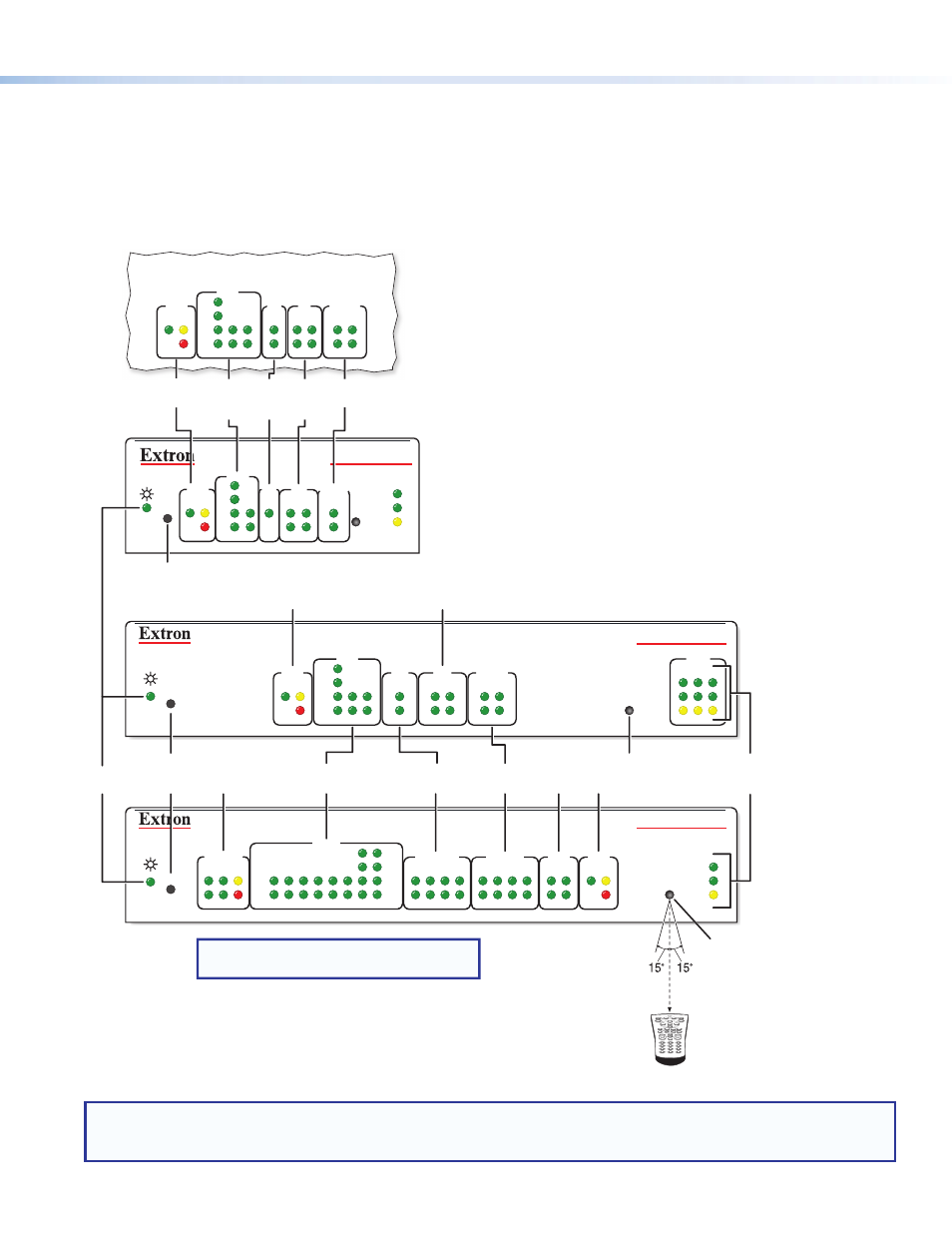
Page 3: Ipcp pro 350, Ipcp pro 550, Reset button, Ir receiver, Lan/ network leds digital i/o leds ipcp pro 350m, Figure 2
3
Panels and Locations of Features
Location and quantity of LEDs and corresponding connectors vary by model, but the functions and port wiring are identical
across models for each port type.
Front Panel Features
R
IPCP PRO 350
1000
LINK
ACT
IR
LAN
1
2
3
2
1
LIMIT
R
IR
Tx
Rx
Tx
Rx
RTS
CTS
COM
IR/SERIAL
RELAYS
FLEX
I/O
S LIMIT
eBUS
SWITCHED
12 VDC
1000
LINK
ACT
IPCP PRO 550
OVER
4
3
1
2
3
4
5
6
7
8
OVER
5
6
7
8
2
1
3
4
2
1
3
4
5
6
7
8
2
1
3
4
COM
I/O
RELAYS
IR/S
3
1
4
2
3
1
4
2
1
2
2
3
1
S LIMIT
eBUS
OVER
Rx
CTS
RTS
Tx
S LIMIT
eBUS
OVER
RTS
1
CTS
Tx
2
Rx
COM
3
1
4
2
I/O
RELAYS
1
2
IR/S
R
1000
LINK
ACT
IR
IPCP PRO 250
S LIMIT
eBUS
OVER
Rx
CTS
RTS
Tx
COM
I/O
RELAYS
IR/S
3
1
4
2
3
1
4
2
1
2
2
3
1
NOTE: Numbers adjacent to LEDs correspond
to the like-numbered rear panel ports.
Switched
12 VDC
LEDs
COM (Serial)
LEDs
COM
(Serial)
LEDs
IR/Serial
LEDs
IR/
Serial
LEDs
Flex I/O
LEDs
Flex
I/O
LEDs
Reset
Button
(recessed)
Reset Button
(recessed)
eBUS LEDs
eBUS
LEDs
Power
LED
IR Receiver
Relay
LEDs
Relay
LEDs
eBUS LEDs
1
2
3
4
5
6
7
8
0
9
2–12"
(4–30 cm)
IR Receiver
IR Learning Angle
and Distance
LAN/
Network
LEDs
Digital I/O LEDs
IPCP Pro 350M
(within another device)
NOTES:
• For reset mode information, see the IPCP Pro Series User Guide.
• The Reset button and power LED for the IPCP Pro 350M are located next to the rear panel connectors.
Figure 2.
IPCP Pro Series Front Panel Features